Deposition device

a deposition device and continuous technology, applied in the direction of electrolysis components, vacuum evaporation coatings, coatings, etc., can solve the problems of difficult maintenance work of the entire device, complex assembly work, and difficult work, and achieve the effect of wide work spa

Inactive Publication Date: 2016-03-10
KOBE STEEL LTD
View PDF4 Cites 4 Cited by
  • Summary
  • Abstract
  • Description
  • Claims
  • Application Information

AI Technical Summary

Benefits of technology

[0008]An object of the present invention is to provide a deposition device provided with a plurality of units including a deposition unit, capable of securing a wide work space for replacement or maintenance of each deposition process device equipped in the deposition unit while arranging these units without overlapping them up and down.

Problems solved by technology

This leads to complexity of assembly work and difficulty in maintenance work of the entire device.
Specifically, when assembling the device, a large-scale work in which, in a state that the heavy upper chamber is lifted by means of a hoist or the like, the lower chamber is installed below and is coupled to the upper chamber is required, but this work is not easy.
Moreover, in replacement or maintenance of each part within the upper chamber, a worker has to work by accessing the upper chamber from the upper side of the upper chamber at a high position, so facility cost for scaffolding for that work and security assurance increases.

Method used


Image

  • Deposition device
  • Deposition device
  • Deposition device

Examples


Embodiment Construction

[0015]Hereinafter, preferred embodiments of the present invention will be described with reference to the drawings.

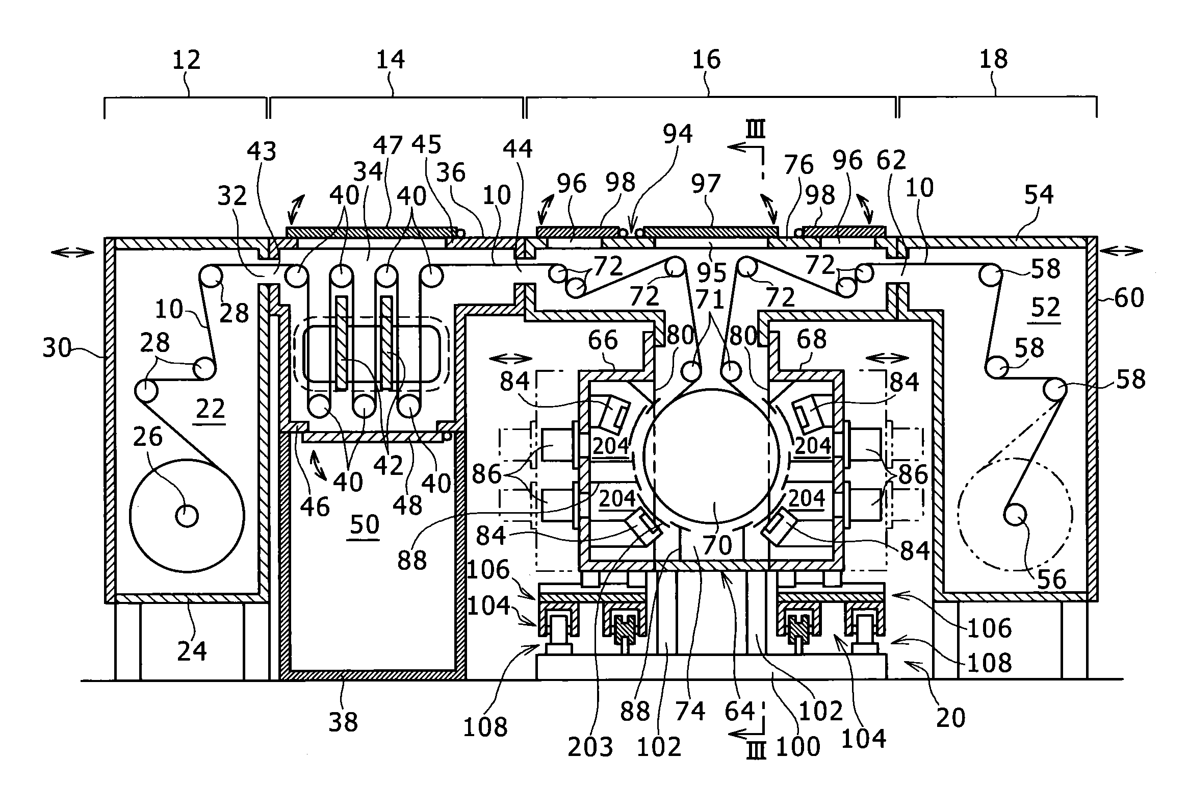
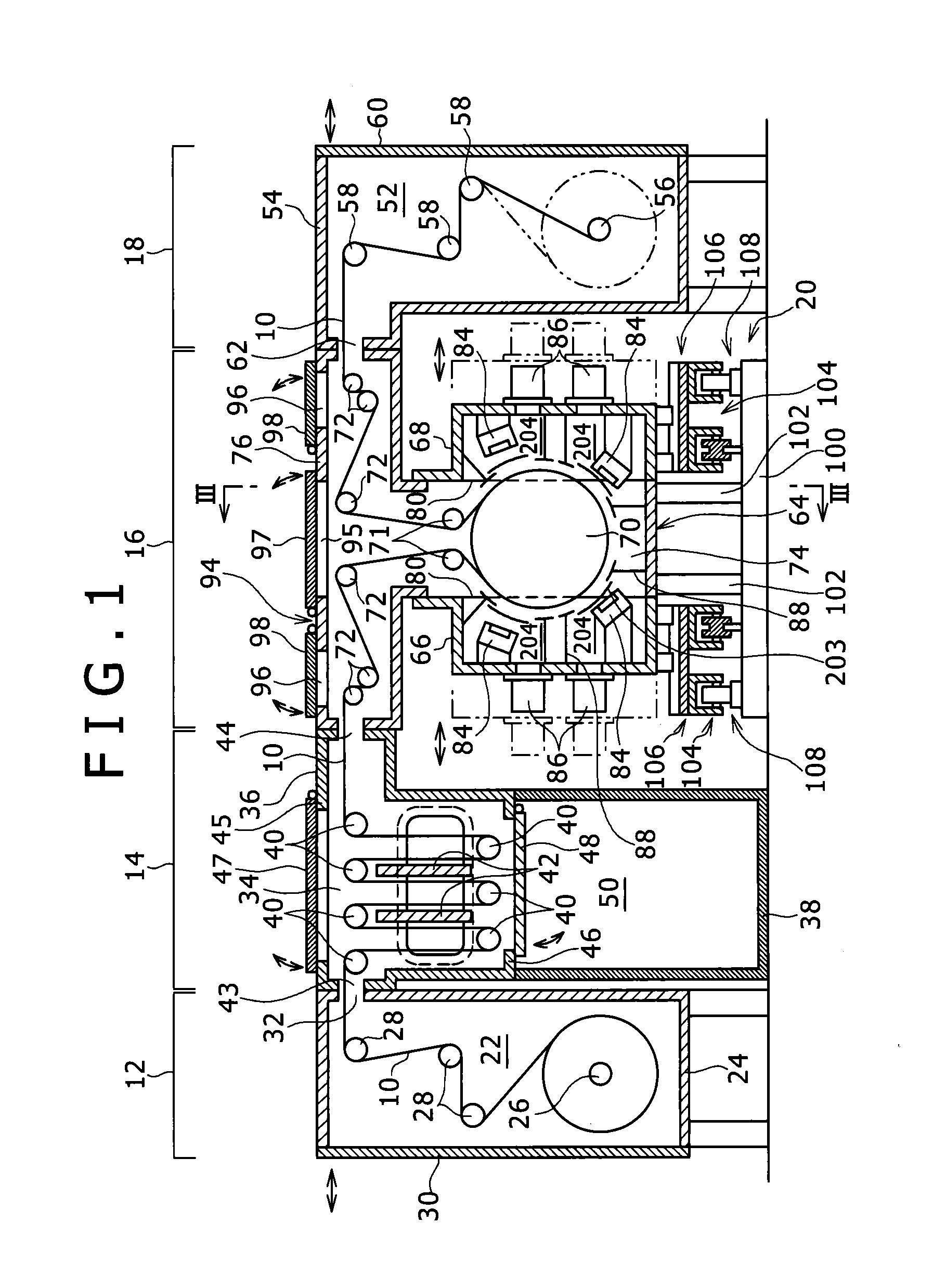
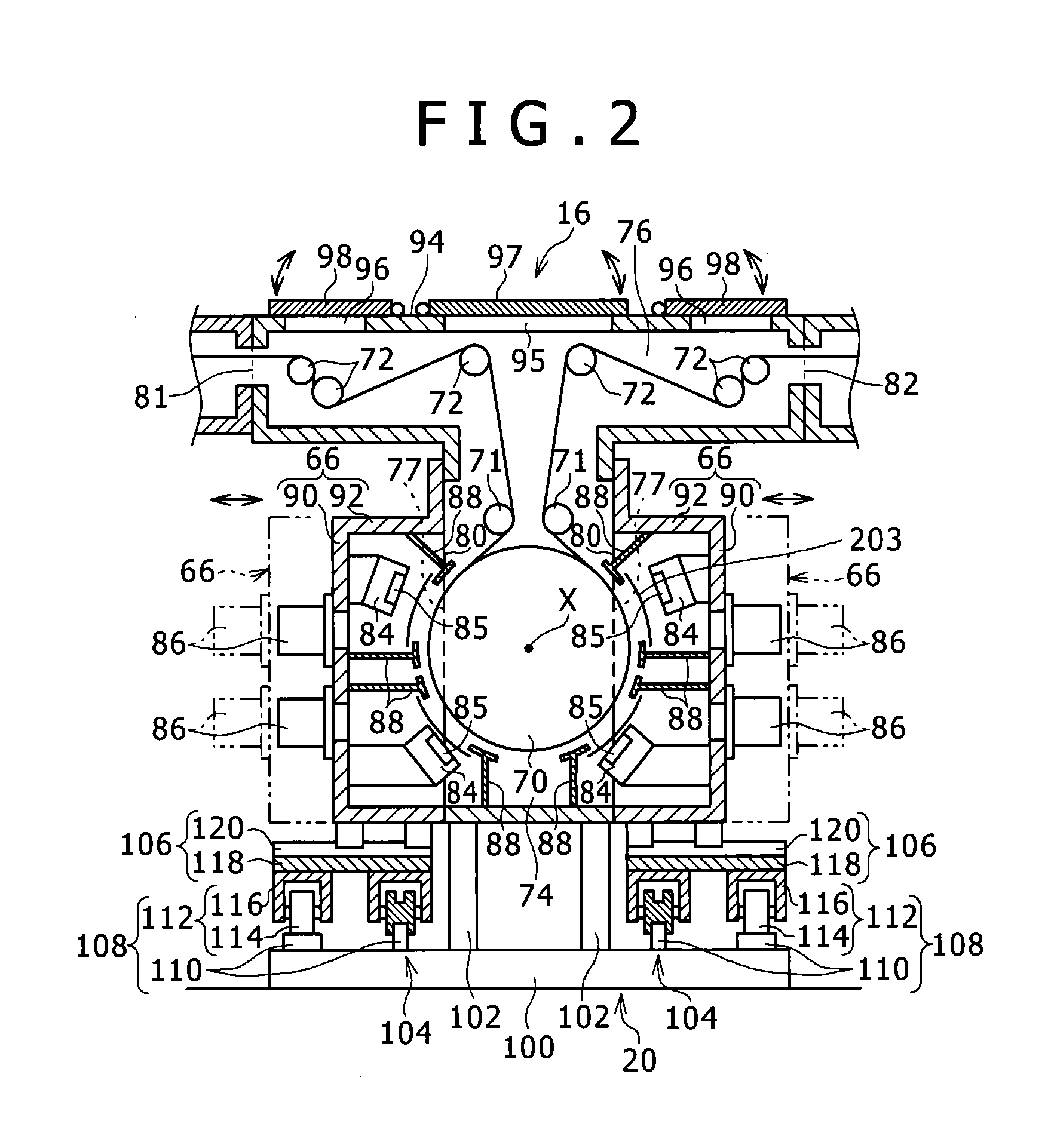
[0016]A deposition device shown in FIG. 1 is a device for forming a thin film on a surface of a long belt-shaped film substrate 10 made of for example a plastic film while conveying the film substrate 10 in the longitudinal direction thereof. The deposition device is provided with a feeding unit 12, a degassing unit 14, a deposition unit 16, and a take-up unit 18 in order of process of the film substrate 10. The units 12, 14, 16, and 18 are sequentially arranged along the horizontal direction which is the conveying direction of the film substrate 10. In the device, the horizontal direction (including the directions somewhat inclined) orthogonal to a rotation center axis X of a deposition roller 70 described later and the direction parallel to the rotation center axis X correspond respectively to the right and left direction and the front and back direction, and the resp...


PUM

PropertyMeasurementUnit
weightaaaaaaaaaa
distanceaaaaaaaaaa
rotationaaaaaaaaaa

Abstract

Provided is a deposition device which can secure work space without vertical overlap of the deposition unit and the units upstream and downstream thereof. This deposition device is provided with a deposition unit (16), and upstream and downstream units (14, 18) arranged to the left and right thereof. The deposition unit (16) is provided with: a deposition roller (70); multiple guide rollers (72); a main chamber (64) having a deposition roller housing unit (74) and, thereabove, a guide roller housing unit (76); first and second process chambers (66, 68) which house multiple deposition process devices (84, 86) to the left and right of the deposition roller housing unit (74); and process chamber support units (104) for supporting the first and second process chambers (66, 68) so as to allow the first and second process chambers (66, 68) to move between a regular position for deposition and a retracted position retracted to the left or right, and between the retracted position and an exposure position separated in the front / back direction.

Description

TECHNICAL FIELD[0001]The present invention relates to a continuous deposition device for forming thin films such as functional thin films on a surface of a belt-shaped film substrate.BACKGROUND ART[0002]Conventionally, as a device for continuously performing deposition to a thin film substrate made of a long film or sheet, there is known a device which continuously conveys the film substrate within a vacuum chamber, and deposits various functional thin films on a surface thereof by sputtering or vapor deposition.[0003]For example, as such a deposition device, Patent Document 1 discloses a device provided with an upper chamber and lower chamber. The lower chamber houses a deposition roller around which a film substrate made of a film or the like can be wound, and a plurality of sputter sources for performing deposition treatment to the film substrate, and the like. The lower chamber has right and left side walls, openings are formed in these side walls, and doors for opening and clos...

Claims


Application Information

Patent Timeline
Patent Type & Authority Applications(United States)
IPC IPC(8): H01J37/32H01J37/34
CPCH01J37/3277H01J37/3417H01J2237/162H01J2237/20278H01J2237/332H01J37/3447C23C14/562H01J37/32513H01J37/32733H01J37/32807H01J37/3288H01J37/32899H01L21/67132
Inventor SEGAWA, TOSHIKIOHBA, NAOKIKUROKAWA, YOSHINORI
Owner KOBE STEEL LTD
Why Eureka
Try Eureka