Rotary electric machine

a rotary electric machine and rotary winding technology, which is applied in the manufacture of inductance/transformer/magnets, dynamo-electric components, and inductance/transformer/magnets, etc., can solve the problems of preventing downsizing complicated cooling construction, and increased axial dimensions so as to reduce the uneven cooling of the coil end, reduce the axial dimension of the rotary electric machine, and reduce the cooling

Active Publication Date: 2016-03-03
MITSUBISHI ELECTRIC CORP
View PDF7 Cites 6 Cited by
  • Summary
  • Abstract
  • Description
  • Claims
  • Application Information

AI Technical Summary

Benefits of technology

The present invention provides a more effective and efficient way to cool a rotary electric machine's armature winding while keeping the machine's size compact. The solution involves inserting a strip-shaped insulating paper between adjacent conductor portions at the coil end, which prevents liquid coolant from flowing out and allows it to flow through the coil end in a balanced and even manner. This results in more uniform cooling of the armature winding, reduces the number of coolant outlets needed, and simplifies the cooling construction. In addition, by eliminating the need for an insulating holder above the coil end, the present invention reduces the axial dimension of the rotary electric machine and enables its downsizing.

Problems solved by technology

However, because it is necessary to form thirteen coolant outlets on the case radially outside the upper half of the coil ends so as to be distributed circumferentially, one problem has been that the cooling construction is complicated.
In addition, because the electric power distributing portion is disposed above the coil end portions of the armature winding, another problem has been that axial dimensions of the rotary electric machine are increased, preventing downsizing of the rotary electric machine.
However, because the liquid coolant is blown onto the coil ends from a direction that is inclined forward in the direction of rotation of the shaft relative to a radial direction, one problem has been that the liquid coolant is less likely to pass through the coil ends and reach the radially outer side, giving rise to uneven cooling in the coil ends, and making cooling of the armature winding poor.

Method used


Image

  • Rotary electric machine
  • Rotary electric machine
  • Rotary electric machine

Examples


embodiment 1

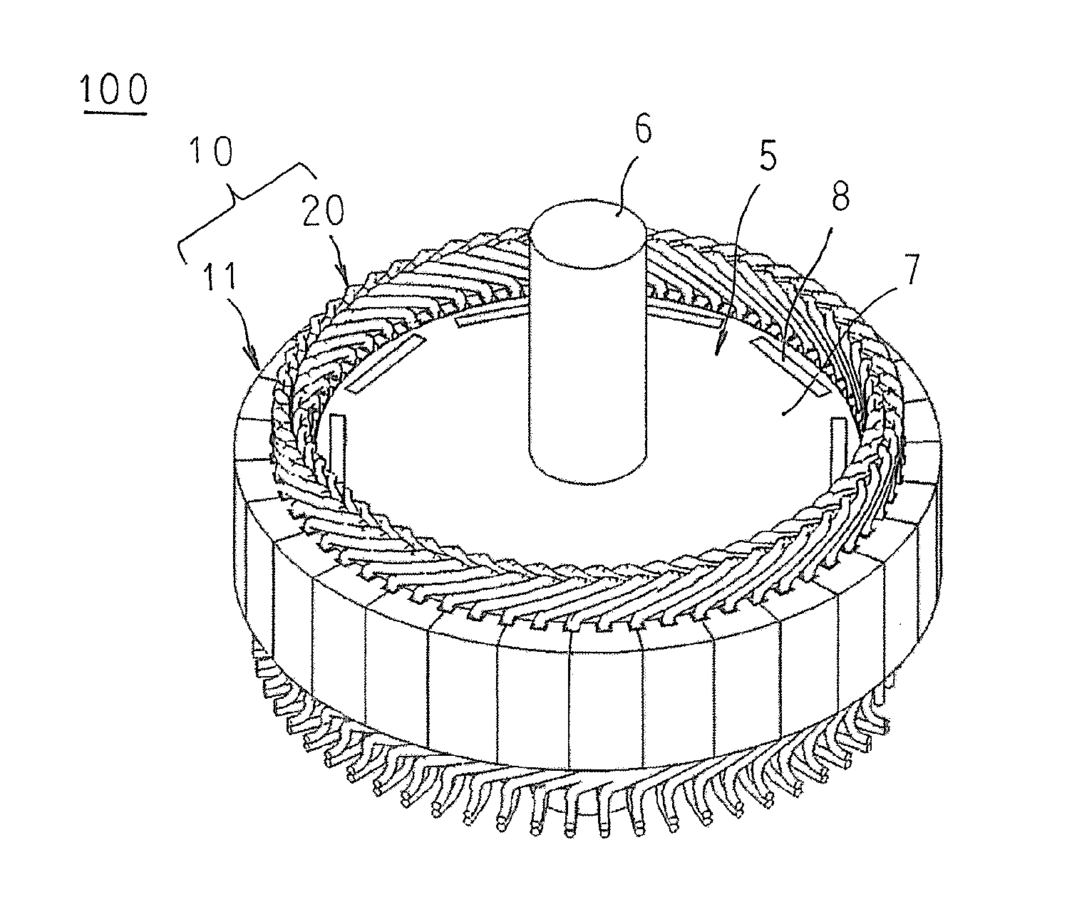
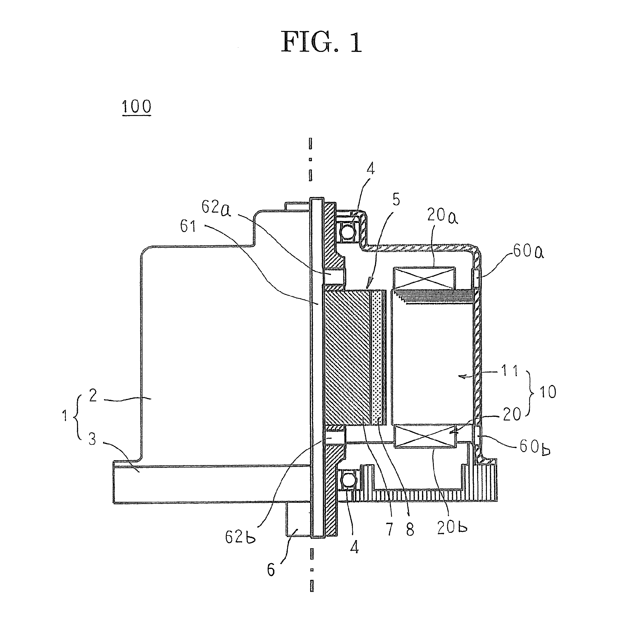
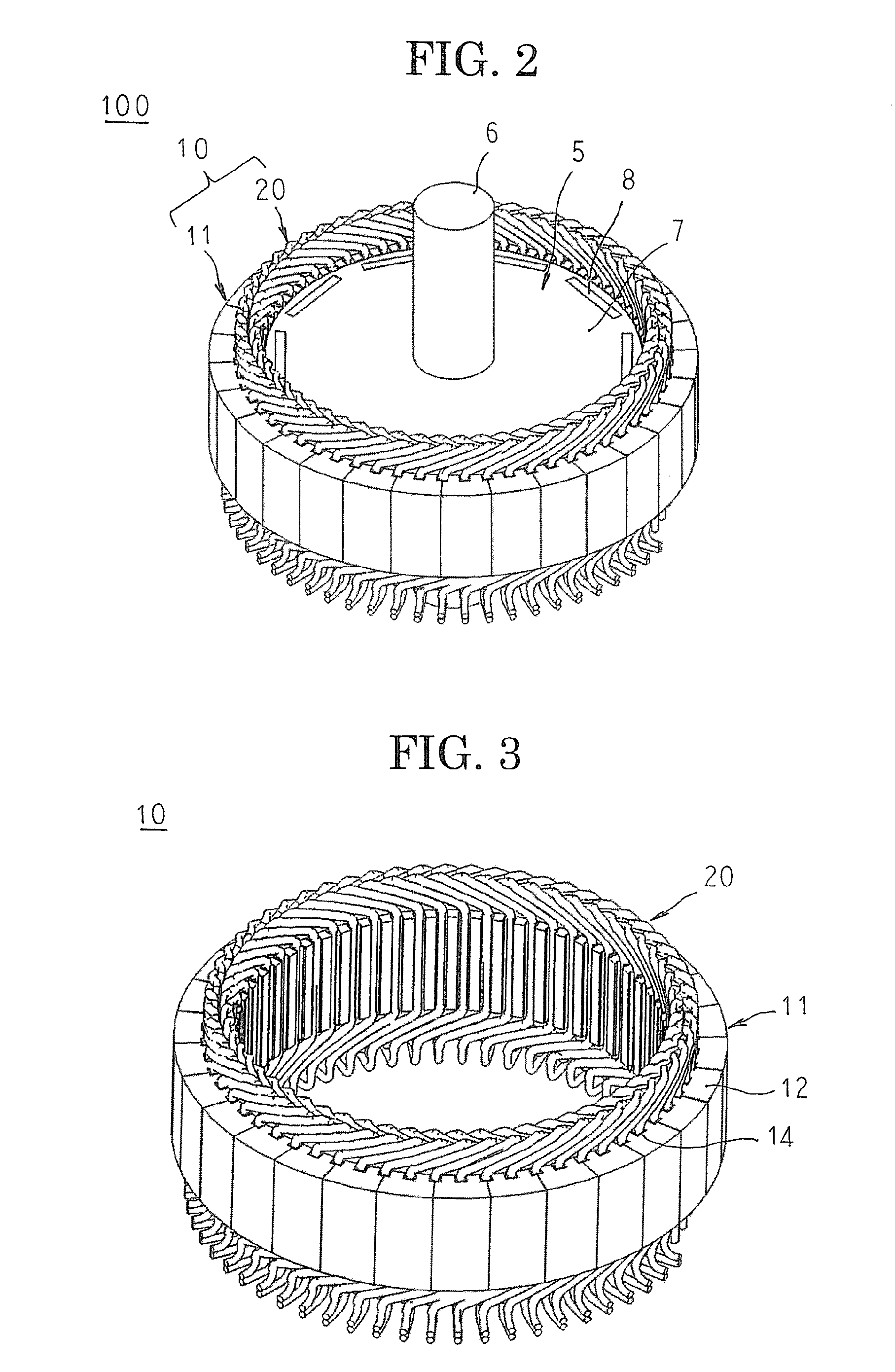
[0032]FIG. 1 is a half section that shows a rotary electric machine according to Embodiment 1 of the present invention, FIG. 2 is an oblique projection that shows part of the rotary electric machine according to Embodiment 1 of the present invention, FIG. 3 is an oblique projection that shows an armature that is used in the rotary electric machine according to Embodiment 1 of the present invention, FIG. 4 is an oblique projection that shows a core block that constitutes the armature that is used in the rotary electric machine according to Embodiment 1 of the present invention, FIG. 5 is an oblique projection that shows a coil that constitutes an armature winding in the rotary electric machine according to Embodiment 1 of the present invention, FIG. 6 is an end elevation that shows the coil that constitutes the armature winding in the rotary electric machine according to Embodiment 1 of the present invention, FIG. 7 is a front elevation that shows the coil that constitutes the armatu...


PUM


Abstract

A rotary electric machine is installed such that a central axis of a rotating shaft is horizontal, and coolant suction apertures are formed at positions on a cylindrical portion of a frame that are vertically above first and second coil ends, and strip-shaped insulating papers are inserted such that a thickness direction is in a radial direction between radially adjacent conductor portions of portions of the conductor wire that constitute the first and second coil ends, and are disposed so as to extend circumferentially across positions that are vertically below the coolant suction apertures inside the first and second coil ends.

Description

BACKGROUND OF THE INVENTION[0001]1. Field of the Invention[0002]The present invention relates to a rotary electric machine such as an electric motor or a generator, for example, and particularly relates to an armature winding cooling construction for a rotary electric machine.[0003]2. Description of the Related Art[0004]In rotary electric machines that are used in electric vehicles, etc., there is demand to be able to pass large currents and continue extended operation at high torque. Since large currents are passed continuously, armature winding temperature increases. Thus, it is important to cool the armature winding effectively such that the armature winding temperature does not exceed a heat tolerance threshold.[0005]In consideration of such conditions, cooling constructions have been proposed in which coil ends of armature windings are cooled directly by a liquid coolant, such as automatic transmission fluid (ATF) oil, for example, during operation (see Patent Literature 1 and ...

Claims


Application Information

Patent Timeline
Patent Type & Authority Applications(United States)
IPC IPC(8): H02K3/38H02K9/00
CPCH02K3/38H02K9/005H02K3/24H02K9/19H02K3/32H01F41/122
Inventor NAKAMURA, MASASHIOKAMOTO, SHOGOINOUE, MASAYASAKAUE, ATSUSHIHINO, TATSURO
Owner MITSUBISHI ELECTRIC CORP
Why Eureka
Try Eureka