
Door frame and molding device for vehicle

a door frame and molding device technology, applied in the field of automotive door frame molding devices, can solve the problems of increased manufacturing cost, inconvenient assembly, increased assembly cost, etc., and achieve the effects of reducing assembly cost, improving assembly quality, and reducing assembly parts

Inactive Publication Date: 2016-03-03
HYUNDAI MOTOR CO LTD
View PDF3 Cites 12 Cited by
  • Summary
  • Abstract
  • Description
  • Claims
  • Application Information

AI Technical Summary

Benefits of technology

The present invention provides an automotive door molding device that makes it possible to reduce the number of assembly parts, improve assembly quality, and reduce manufacturing cost. This is achieved by improving the design of the vertical width of a variable frame molding and the assembly structure between the door frame and the variable frame molding. Firstly, the upper part of the vertical width of the variable frame molding over the connection support of the door frame has a constant vertical width, while the lower part gradually increases in vertical width as it goes rearward, which results in the integrally formed door weather strip and parting weather strip, reducing the number of parts. Secondly, a fastening protrusion fastened to the door frame by a clip is integrally formed on the inner side of the vertical frame molding, ensuring a more secure attachment and preventing coming-off of the variable frame molding due to water pressure in car washing. Lastly, an outer glass run supporting the outer side of a glass is integrally formed on the inner side of the bottom of the variable frame molding, preventing the phenomenon that the outer glass run integrally formed in a run channel from being pulled up and reducing the supporting force that keeps it in close contact with the glass.

Problems solved by technology

Second, in addition to the door frame, there are too many parts mounted on the door frame, so assemblage is inconvenient and the manufacturing cost increases.
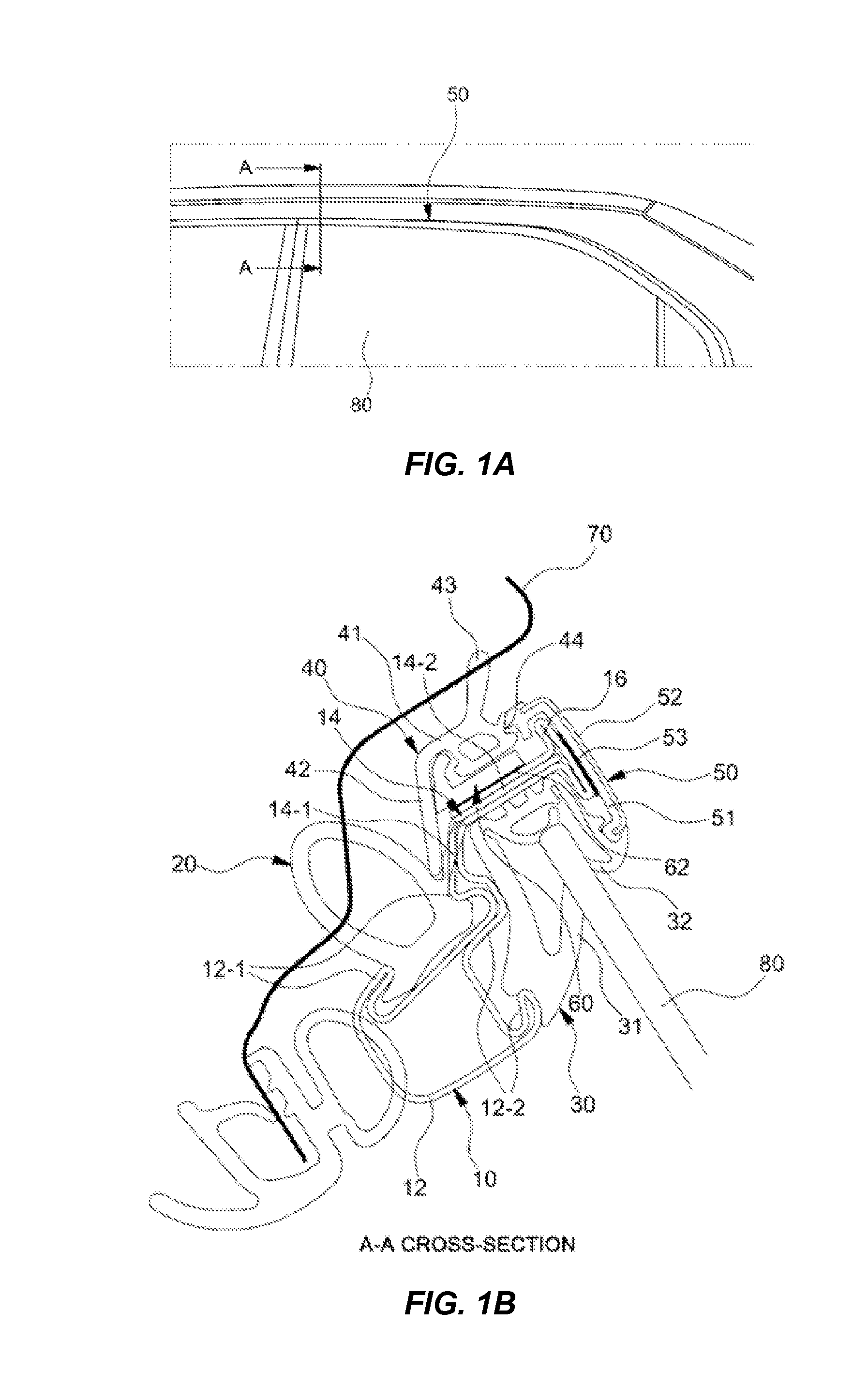
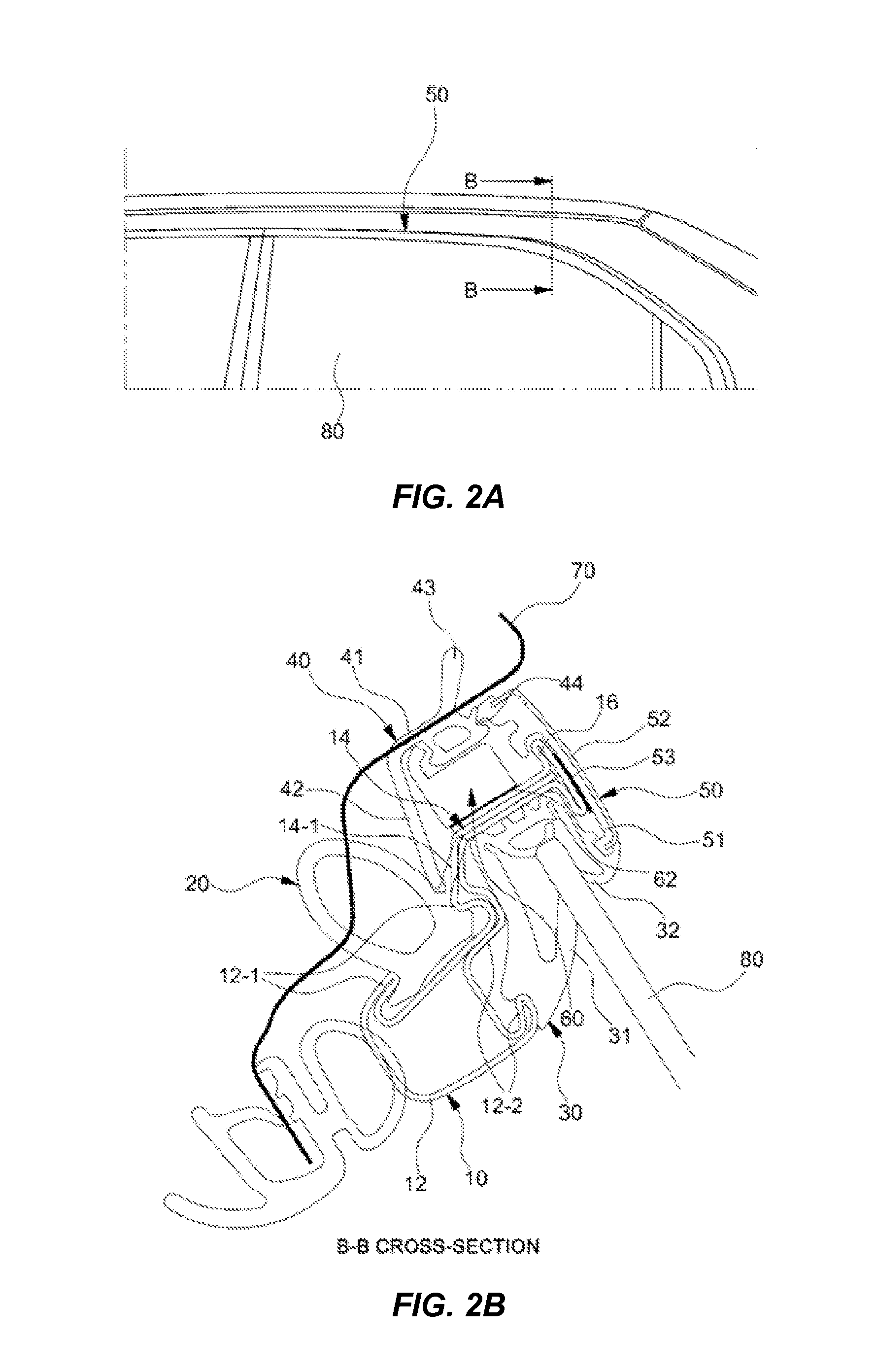
That is, there are too many parts, including the door weather strip 20, the run channel 30, the parting weather strip 40, the variable frame molding 50, the mounting molding 60, the double-sided tape 62 for attaching the mounting molding 60, and the bonding member 53 for attaching the variable frame molding 50, so assemblage is inconvenient and the manufacturing cost increases.

Method used


Image

  • Door frame and molding device for vehicle
  • Door frame and molding device for vehicle
  • Door frame and molding device for vehicle

Examples


Embodiment Construction

[0057]Reference will now be made in detail to various embodiments of the present invention(s), examples of which are illustrated in the accompanying drawings and described below. While the invention(s) will be described in conjunction with exemplary embodiments, it will be understood that the present description is not intended to limit the invention(s) to those exemplary embodiments. On the contrary, the invention(s) is / are intended to cover not only the exemplary embodiments, but also various alternatives, modifications, equivalents and other embodiments, which may be included within the spirit and scope of the invention as defined by the appended claims.

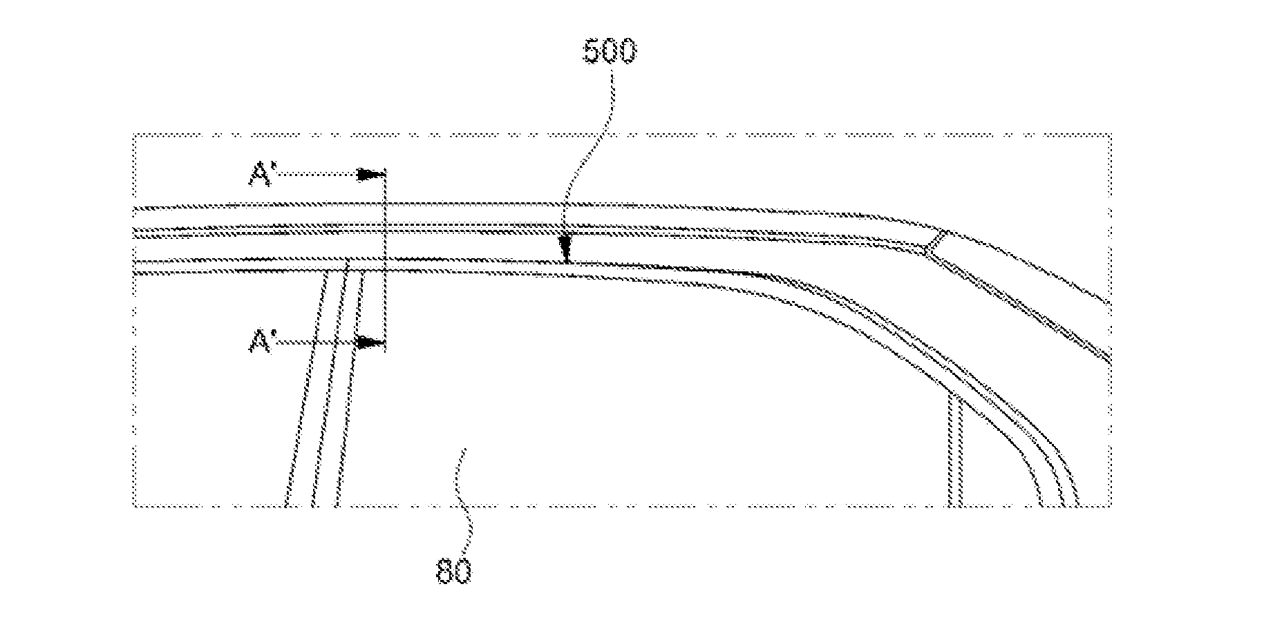
[0058]In the accompanying drawings, FIG. 4A and FIG. 4B are cross-sectional views illustrating the front portion of a door frame molding device according to the present invention and FIG. 5A and FIG. 5B are cross-sectional views illustrating the rear portion of the door frame molding device according to the present invention.

[0059...


PUM


Abstract

An automotive door molding device, may include a door frame composed of an inner support formed with a space therein by foaming, a connection support extending from an outer upper end of the inner support and horizontally arranged, and a variable frame molding support vertically bending upward from an outer end of the connection support, an integral weather strip disposed on the inner support and the connection support of the door frame, a run channel having an inner glass run supporting an inner side of a glass and disposed on an outer side and a bottom of the inner support of the door frame, and a variable frame molding fastened to a bottom of the connection support, in close contact with the variable frame molding support of the door frame.

Description

CROSS-REFERENCE TO RELATED APPLICATION[0001]The present application claims priority to Korean Patent Application No. 10-2014-0112856 filed Aug. 28, 2014, the entire contents of which is incorporated herein for all purposes by this reference.BACKGROUND OF THE INVENTION[0002]1. Field of the Invention[0003]The present disclosure relates to an automotive door frame molding device. More particularly, it relates to an automotive door molding device that allows for improvement of assembly quality and reduction of the manufacturing cost by improving the assembly cross-sectional structure between a door frame and a variable frame molding.[0004]2. Description of Related Art[0005]A variable frame molding 50, of which the vertical width changes, as it goes in the longitudinal direction of a car body, is mounted, as a kind of external ornament, on the outer side of a door frame being in contact with the top of door glasses of a vehicle, as illustrated in FIG. 1A, FIG. 1B, FIG. 2A and FIG. 2B.[00...

Claims


Application Information

Patent Timeline
Patent Type & Authority Applications(United States)
IPC IPC(8): B60J10/00
CPCB60J10/088B60J10/0002B60J10/08B60J10/0048B60J10/0062B60J10/002B60J5/0402B60J10/265B60J10/36B60J10/76B60J10/88B60J10/15B60J10/22B60J10/26B60J10/30B60J10/80
Inventor NAM, YONG, HYUN
Owner HYUNDAI MOTOR CO LTD
Learn More