
Configurable Medical Video Safety System

Active Publication Date: 2016-03-03
KARL STORZ IMAGING INC
View PDF11 Cites 6 Cited by
  • Summary
  • Abstract
  • Description
  • Claims
  • Application Information

AI Technical Summary

Benefits of technology

The present invention provides an operating room system that allows an anesthesiologist to quickly and efficiently intubate a patient using a video laryngoscope. The video laryngoscope provides a video feed to a display positioned in the operating room, allowing the anesthesiologist to easily see the video display so as to intubate the patient. The video feed can be switched quickly and easily between multiple different imaging sources, such as an endoscope and laryngoscope, without the need for additional equipment. The interface allows the anesthesiologist to override the routing of the surgical image data to the display and automatically route the laryngoscope image data to a display for the anesthesiologist to utilize for the intubation process. This reduces the time the patient is under anesthesia and minimizes the intubation time.

Problems solved by technology

It is estimated that between one in 6,000 to one in 8,000 general anesthesia procedures result in death.
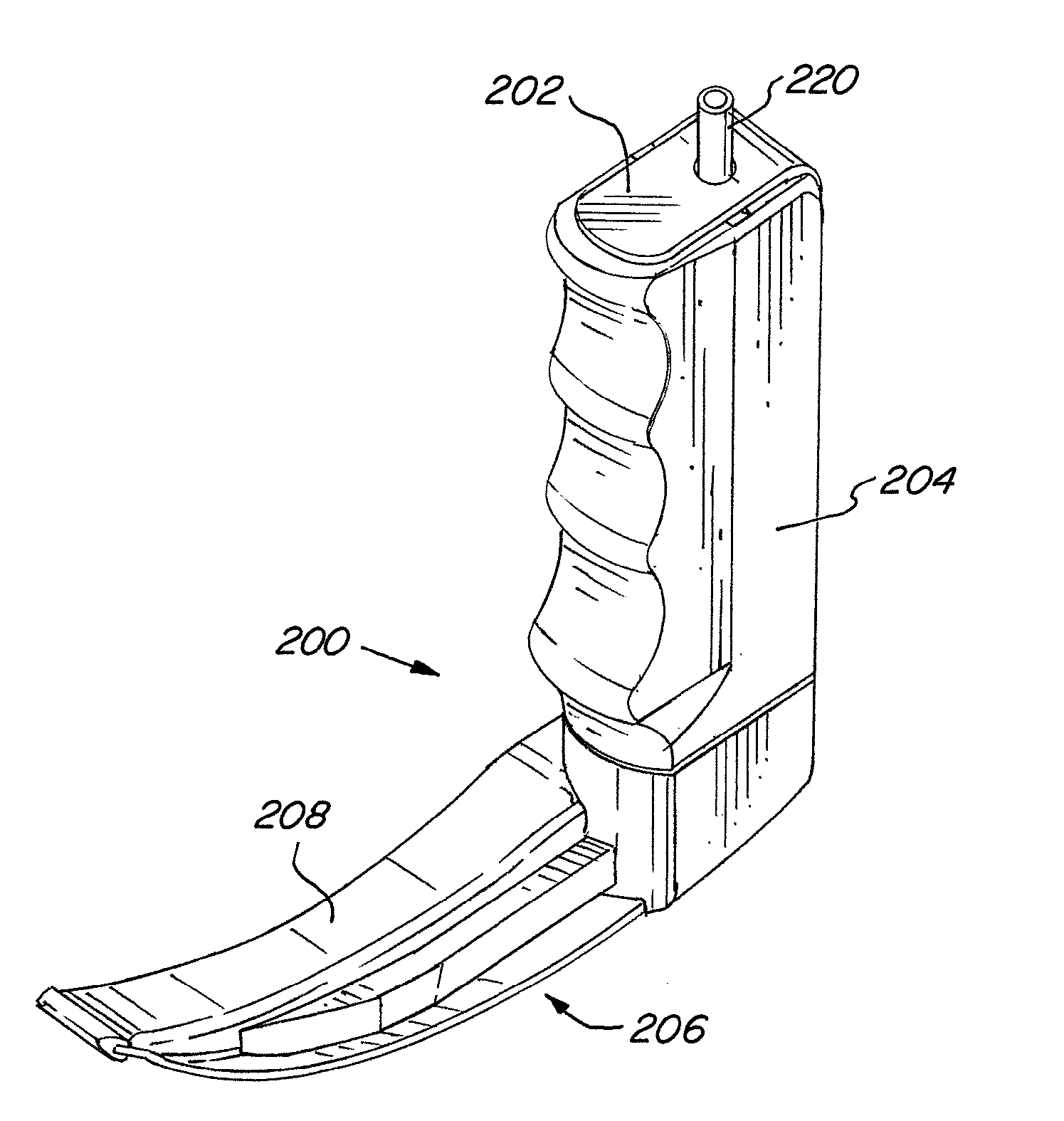
Some obstacles encountered by the anesthesiologist upon insertion of the endotracheal tube include the remoteness of the location where the tube is to be positioned, the consequent restriction of view as the tube is inserted, variations and anomalies in the anatomy of the patients, an uncomfortable and unnatural position for the anesthesiologist while holding the instrument, the potential need to change blades during the procedure, and the necessity for rapid intubation.
While steps have been made in the presentation of endoscope video imaging in an operating room system, the integration of video laryngoscopes into the operating room control system has not been effectively addressed.
However, if during a surgical procedure it becomes necessary to re-intubate the patient, time is critical.
Requiring moving the operating room equipment aside, moving the laryngoscope equipment in its place, intubating the patient, moving the laryngoscope equipment aside and moving the operating room equipment back into place can often lead to delayed time to intubate the patient and increased time under anesthesia, both of which are highly undesirable.
Likewise, the necessity of having to program the routing of the image data that is generated by the laryngoscope wastes valuable time that the patient is disconnected from the ventilation machine and not breathing.
It also disadvantageously extends the time the patient is maintained under general anesthesia.

Method used


Image

  • Configurable Medical Video Safety System
  • Configurable Medical Video Safety System
  • Configurable Medical Video Safety System

Examples


Embodiment Construction

[0066]Referring now to the drawings, wherein like reference numerals designate corresponding structure throughout the views.

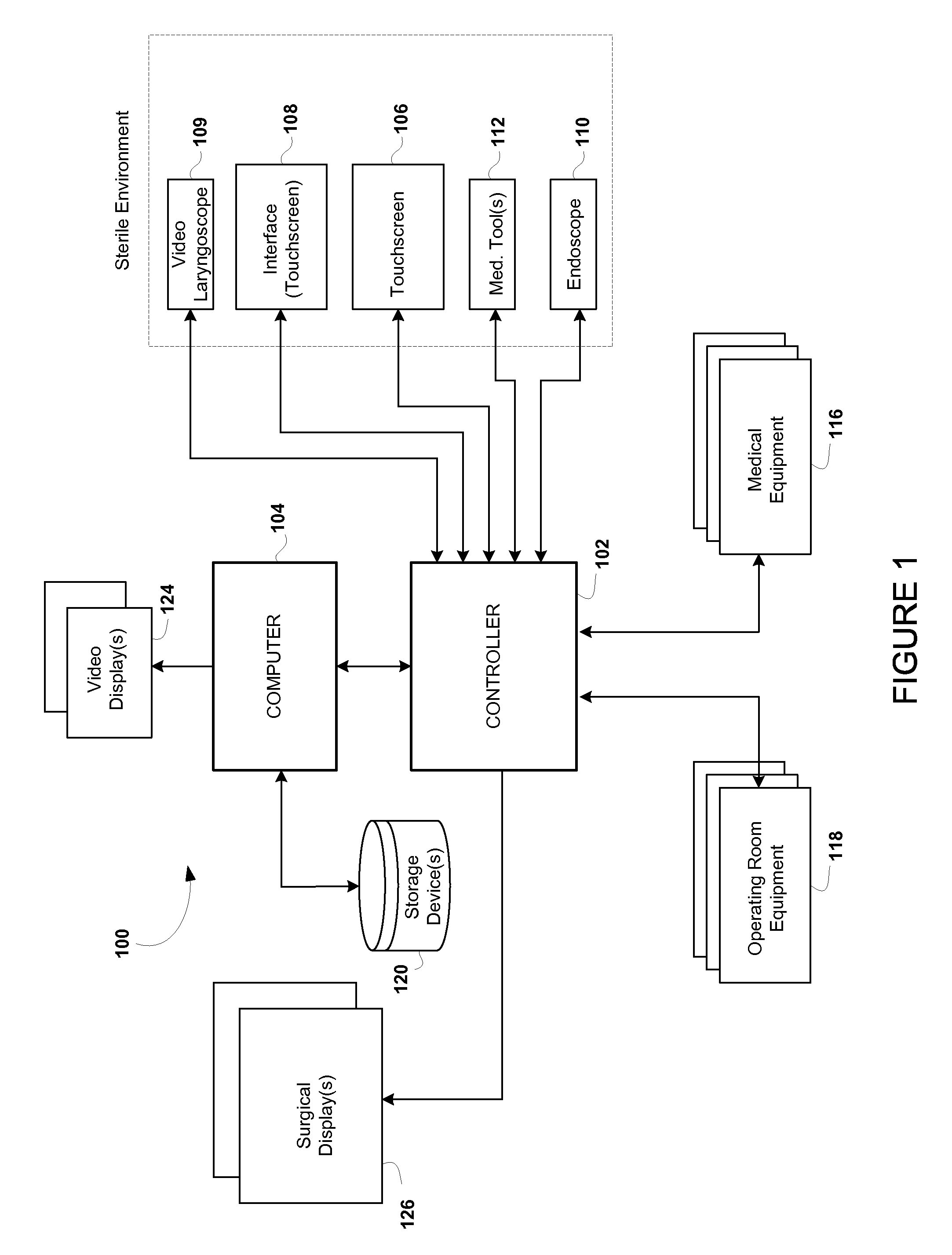
[0067]FIG. 1 is a block diagram of operating room control system 100 that generally includes a controller 102 connected to a computer 104. The controller 102 would typically be positioned or located in the operating room in proximity to the various equipment connected thereto and in one embodiment, would be rack-mounted. It is further understood that computer 104 may also be located in the operating room and rack-mounted, however, this is not required as the controller 102 could be coupled to computer 104 via, for example, a network connection.

[0068]Connected to controller 102 is touch screen 106, which provides an interface for a user to control and to interface with operating room control system 100. Touch screen 106 is shown positioned in the sterile environment and is accessible by a surgeon performing a procedure. The touch screen 106 may comprise virtuall...


PUM


Abstract

A medical image routing system that allows for a user to override the current routing of medical image data such that a user need only activate an interface to automatically interrupt the the first medical image data routing to a display(s) with the second medical image data automatically routed to the display(s). Upon activation of the interface a second time, the first medical image data routing is automatically reestablished and the second medical image data is automatically interrupted.

Description

FIELD OF THE INVENTION[0001]The system relates to an image routing system, and more particularly to a medical image routing system utilized in an operating room providing prioritized image routing.BACKGROUND OF THE INVENTION[0002]A wide variety of operating room systems are known for performing both diagnostic and surgical procedures. In particular, systems have been provided that allow a surgeon to perform a procedure with a variety of medical and operating room equipment. This equipment ranges from visual imaging tools (e.g., endoscopes, cameras, digital x-ray, ultrasound, computer tomography, magnetic resonance imaging, etc.) and systems, to medical devices (e.g. tools for cutting, grasping, extracting, irrigating, etc.), and other operating room equipment.[0003]In particular systems, operating room visualization equipment has been provided that allows for visualization of the interior of an organ or joint while a surgeon is conducting a procedure. These visualization systems all...

Claims


Application Information

Patent Timeline
IPC IPC(8): A61B1/267A61B1/00A61B1/045G06F3/01G06F3/041G06F3/0481G06F3/147G06F3/16G16H20/40G16H30/20G16H30/40G16H40/67G16Z99/00
CPCA61B1/0005A61B1/267G06F3/167G06F3/147A61B1/00087G06F3/017G06F3/041A61B1/045A61B1/00045G06F3/04817G06F3/0346G16H20/40G16H30/20G16H40/67G16H30/40G16Z99/00
Inventor SELCHO, MICHAELHILZINGER, HANS-UWEBREAM, DEVON
Owner KARL STORZ IMAGING INC
Learn More