
Method and system for use in configuring multiple near field antenna systems

a near field antenna and configuration method technology, applied in the direction of circuit arrangement, inductance, transmission, etc., can solve the problems of user being unable to effectively use a device, user may have to limit their use of a device, and the battery power is often critical

Inactive Publication Date: 2016-02-18
SONY CORP +1
View PDF1 Cites 15 Cited by
  • Summary
  • Abstract
  • Description
  • Claims
  • Application Information

AI Technical Summary

Benefits of technology

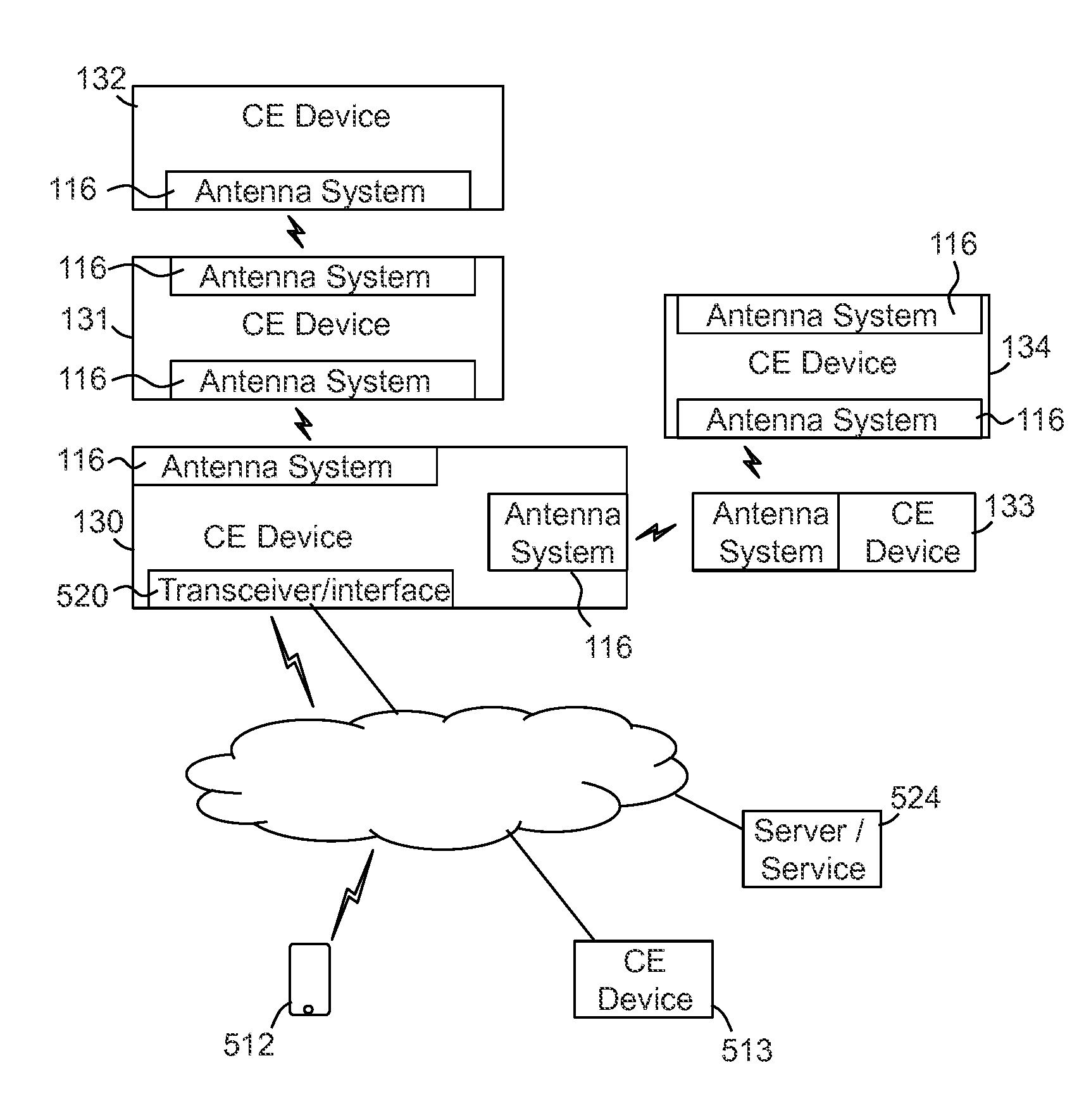
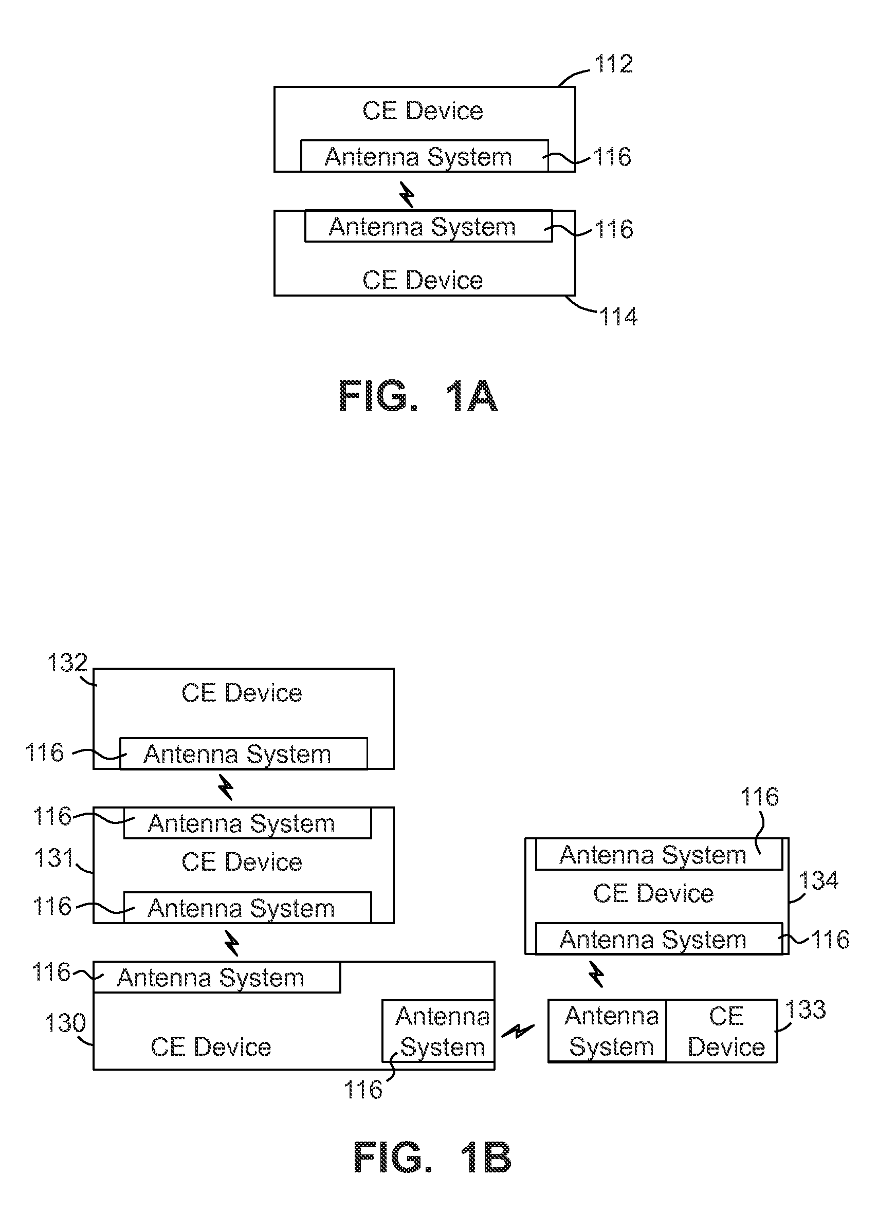
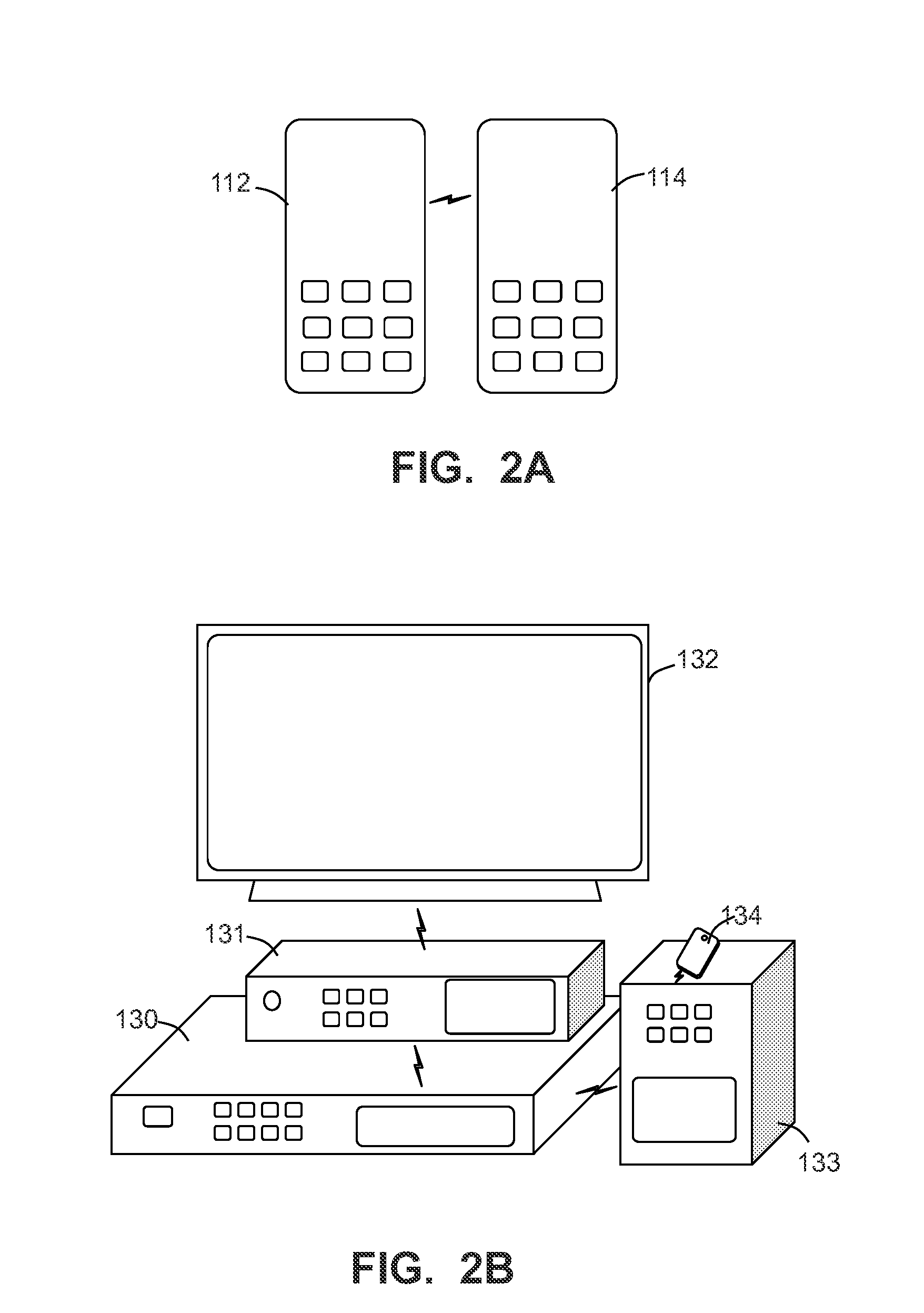
The patent text describes methods, processes, apparatuses, and systems for configuring networks using near field wireless antenna systems. The technical effects of the patent include providing wireless electrical power transfer and enabling wireless communication between consumer electronic devices through the use of multiple antenna systems. The wireless coupling parameters of each antenna system are determined, and wireless coupling configurations are determined which dictate which antenna systems should communicate with each other. These configurations can be initiated through a communication of one or more configuration instructions. Overall, the patent provides a solution for configuring networks using near field wireless antenna systems.

Problems solved by technology

As such, battery power is often critical.
In many instances, a user may have to limit their use of a device because of limited remaining power.
Similarly, a user may be unable to effectively use a device because of a lack of power stored on the device.

Method used


Image

  • Method and system for use in configuring multiple near field antenna systems
  • Method and system for use in configuring multiple near field antenna systems
  • Method and system for use in configuring multiple near field antenna systems

Examples


Embodiment Construction

[0022]The following description is not to be taken in a limiting sense, but is made merely for the purpose of describing the general principles of exemplary embodiments. The scope of the invention should be determined with reference to the claims.

[0023]Reference throughout this specification to “one embodiment,”“an embodiment,”“some embodiments,”“some implementations” or similar language means that a particular feature, structure, or characteristic described in connection with the embodiment is included in at least one embodiment of the present invention. Thus, appearances of the phrases “in one embodiment,”“in an embodiment,”“in some embodiments,” and similar language throughout this specification may, but do not necessarily, all refer to the same embodiment.

[0024]Furthermore, the described features, structures, or characteristics of the invention may be combined in any suitable manner in one or more embodiments. In the following description, numerous specific details are provided,...


PUM


Abstract

Some embodiments provide a method of configuring a near field wireless network are provided, comprising: identifying a plurality of near field antenna systems including a first, second and third antenna systems, wherein the first antenna system is cooperated with a first consumer electronic (CE) device and the second antenna system is cooperated with a second CE device, wherein each of the plurality of antenna systems comprises a power transfer antenna and one or more communications antennas; receiving wireless coupling parameters corresponding to the antenna systems; determining wireless coupling configurations configured to dictate which of the antenna systems each of the first, second and third antenna systems is to directly communicate with; and initiating a communication of one or more configuration instructions directing each of the plurality of antenna systems to be configured in accordance with the determined wireless coupling configurations.

Description

[0001]This application relates to U.S. application Ser. No. 14 / 290,409, filed on May 29, 2014, for McCoy et al., and entitled PORTABLE DEVICE TO PORTABLE DEVICE WIRELESS POWER TRANSFER METHODS AND SYSTEMS (Attorney Docket No. 9212-132381-US), and U.S. application Ser. No. 14 / 290,429, filed on May 29, 2014, for Milne et al., and entitled SCALABLE ANTENNA SYSTEM (Attorney Docket No.: 9212-132793-US), all of which are incorporated in their entirety herein by reference.BACKGROUND[0002]1. Field of the Invention[0003]The present invention relates generally to consumer electronic devices, and more specifically to powering portable consumer electronic devices.[0004]2. Discussion of the Related Art[0005]The number and types of consumer electronic devices continues to increase. Further, many of these consumer electronic devices are portable. As such, battery power is often critical.[0006]In many instances, a user may have to limit their use of a device because of limited remaining power. Simi...

Claims


Application Information

Patent Timeline
Patent Type & Authority Applications(United States)
IPC IPC(8): H04B5/00H02J5/00
CPCH02J5/005H04B5/0037H02J50/20H04B5/72H04B5/79
Inventor MCCOY, CHARLESMILNE, JAMES R.XIONG, TRUE
Owner SONY CORP
Learn More