Control apparatus for internal combustion engine
a control apparatus and internal combustion engine technology, applied in the direction of electric control, ignition automatic control, speed sensing governors, etc., can solve the problems of inability to achieve a sufficient torque reduction and combustion may become unstabl
- Summary
- Abstract
- Description
- Claims
- Application Information
AI Technical Summary
Benefits of technology
Problems solved by technology
Method used
Image


Examples
first embodiment
Configuration of First Embodiment
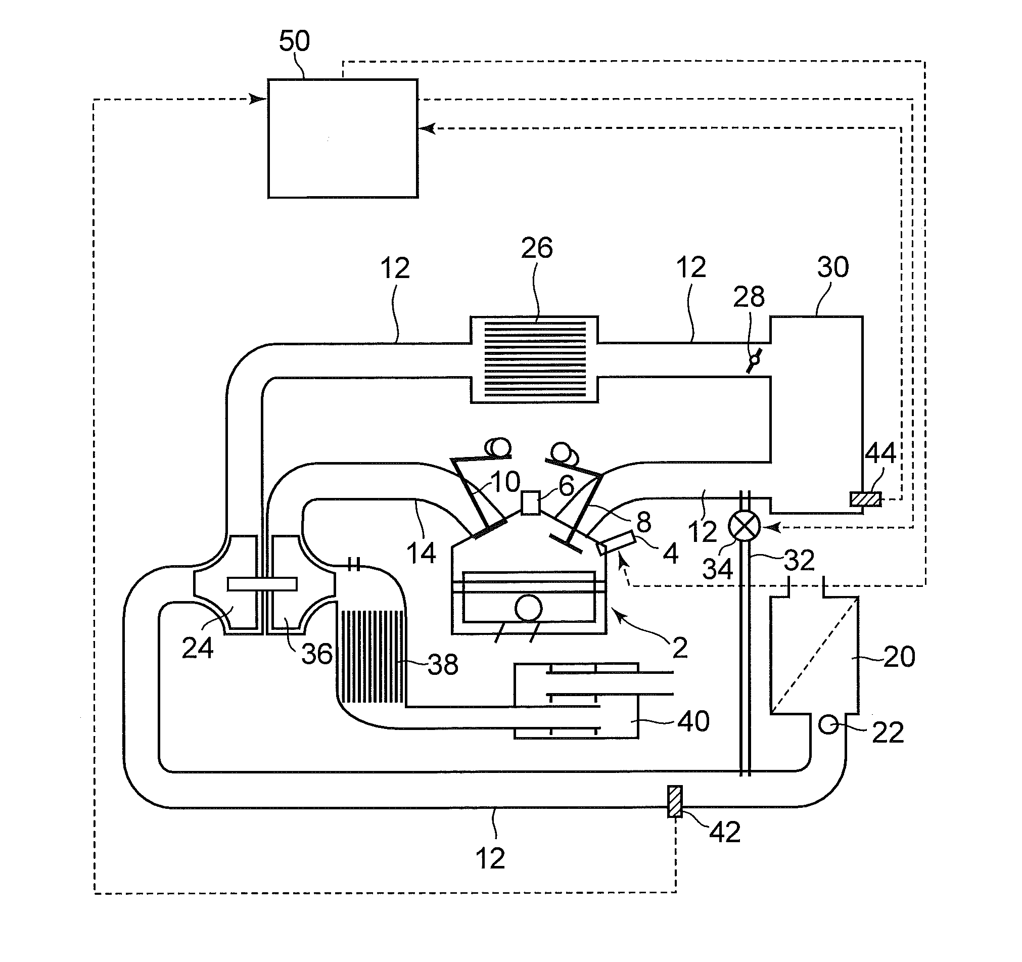
[0036]FIG. 1 is a schematic diagram illustrating a configuration of a system according to a first embodiment of the invention. The system according to this embodiment includes a spark ignition type internal combustion engine 2 that serves as an application subject of a control apparatus. The internal combustion engine 2 uses gasoline as fuel, and can be used favorably as a power source of a vehicle, for example. The internal combustion engine 2 can be switched between a stoichiometric combustion operation, in which an air-fuel mixture having an air-fuel ratio in the vicinity of the stoichiometric air-fuel ratio is burned, and a lean burn operation, in which an air-fuel mixture having a much leaner air-fuel ratio than the stoichiometric air-fuel ratio is burned in a predetermined lean burn operation region. Further, FIG. 1 shows only one cylinder of the internal combustion engine 2, but the internal combustion engine 2 includes a plurality of cylinde...
second embodiment
[0066]FIG. 5 is a view illustrating a system according to a second embodiment of the invention. As shown in FIG. 5, the system of FIG. 5 includes a high pressure EGR apparatus, but is otherwise configured identically to the system of FIG. 1. More specifically, the system of FIG. 5 includes, in addition to the system of FIG. 1, a high pressure EGR (HPL-EGR: High Pressure Loop Exhaust Gas Recirculation) apparatus that recirculates a part of the exhaust gas from the exhaust passage 14 to the intake passage 12 as EGR gas.
[0067]The high pressure EGR apparatus includes a high pressure EGR pipe 60, and a high pressure EGR cooler 62 and a high pressure EGR valve 64 provided in the high pressure EGR pipe 60. One end of the high pressure EGR pipe 60 is connected to the exhaust passage 14 on the upstream side of the exhaust turbine 36, and another end is connected to the intake passage 12 between the surge tank 30 and an intake manifold (not shown). By adjusting an opening of the high pressure...
third embodiment
[0078]FIG. 7 is a view illustrating an overall configuration of a system according to a third embodiment of the invention. The system shown in FIG. 7 includes a low pressure EGR apparatus, but is otherwise identical to the system shown in FIG. 1. The system of FIG. 7 includes a low pressure EGR (LPL-EGR: Low Pressure Loop Exhaust Gas Recirculation) apparatus.
[0079]In the system of FIG. 7, the low pressure EGR apparatus includes a low pressure EGR pipe 66, and a low pressure EGR cooler 68 and a low pressure EGR valve 70 provided in the low pressure EGR pipe 66. One end of the low pressure EGR pipe 66 is connected to the exhaust passage 14 on the downstream side of the catalyst 38, and another end is connected to the intake passage 12 on the upstream side of the compressor 24. By adjusting an opening of the low pressure EGR valve 70, the low pressure EGR valve 70 can modify the flow passage sectional area of the low pressure EGR pipe 66. In other words, the flow rate of EGR gas flowin...
PUM
 Abstract
Description
Claims
Application Information
 - R&D
- Intellectual Property
- Life Sciences
- Materials
- Tech Scout
- Unparalleled Data Quality
- Higher Quality Content
- 60% Fewer Hallucinations
Browse by: Latest US Patents, China's latest patents, Technical Efficacy Thesaurus, Application Domain, Technology Topic, Popular Technical Reports.
© 2025 PatSnap. All rights reserved.Legal|Privacy policy|Modern Slavery Act Transparency Statement|Sitemap|About US| Contact US: help@patsnap.com