Switched reluctance motor

Active Publication Date: 2016-02-11
TOYOTA JIDOSHA KK +1
View PDF0 Cites 3 Cited by
  • Summary
  • Abstract
  • Description
  • Claims
  • Application Information

AI Technical Summary

Benefits of technology

The present invention provides a motor that uses switched reluctance techniques. The motor has a stator with stator teeth and a rotor with rotor teeth. The stator teeth have winding wire wound around them. A driving circuit applies a current to the winding wire for each phase. A control device controls the driving circuit. The control device performs two functions: starting rising of the current at a specific time when the change in inductance of the winding wire with respect to the change in rotational angle of the rotor is from negative to positive, and controlling the current to ensure that a certain product is not smaller than a predetermined value. This ensures that the magnetic attractive force between the stator and rotor teeth is not larger than a specific target value. This motor design reduces the size and complexity of conventional motors and makes them more efficient.

Problems solved by technology

However, since the conventional switched reluctance motor gradually changes the magnetic attractive force, this deteriorates efficiency while decreasing the noise and vibration.

Method used


Image

  • Switched reluctance motor
  • Switched reluctance motor
  • Switched reluctance motor

Examples


Embodiment Construction

[0030]An embodiment of a switched reluctance motor according to the present invention is hereinafter described in detail with reference to the drawings. Meanwhile, the invention is not limited by the embodiment.

[0031]An embodiment of a switched reluctance motor according to the present invention is described with reference to FIGS. 1 to 11.

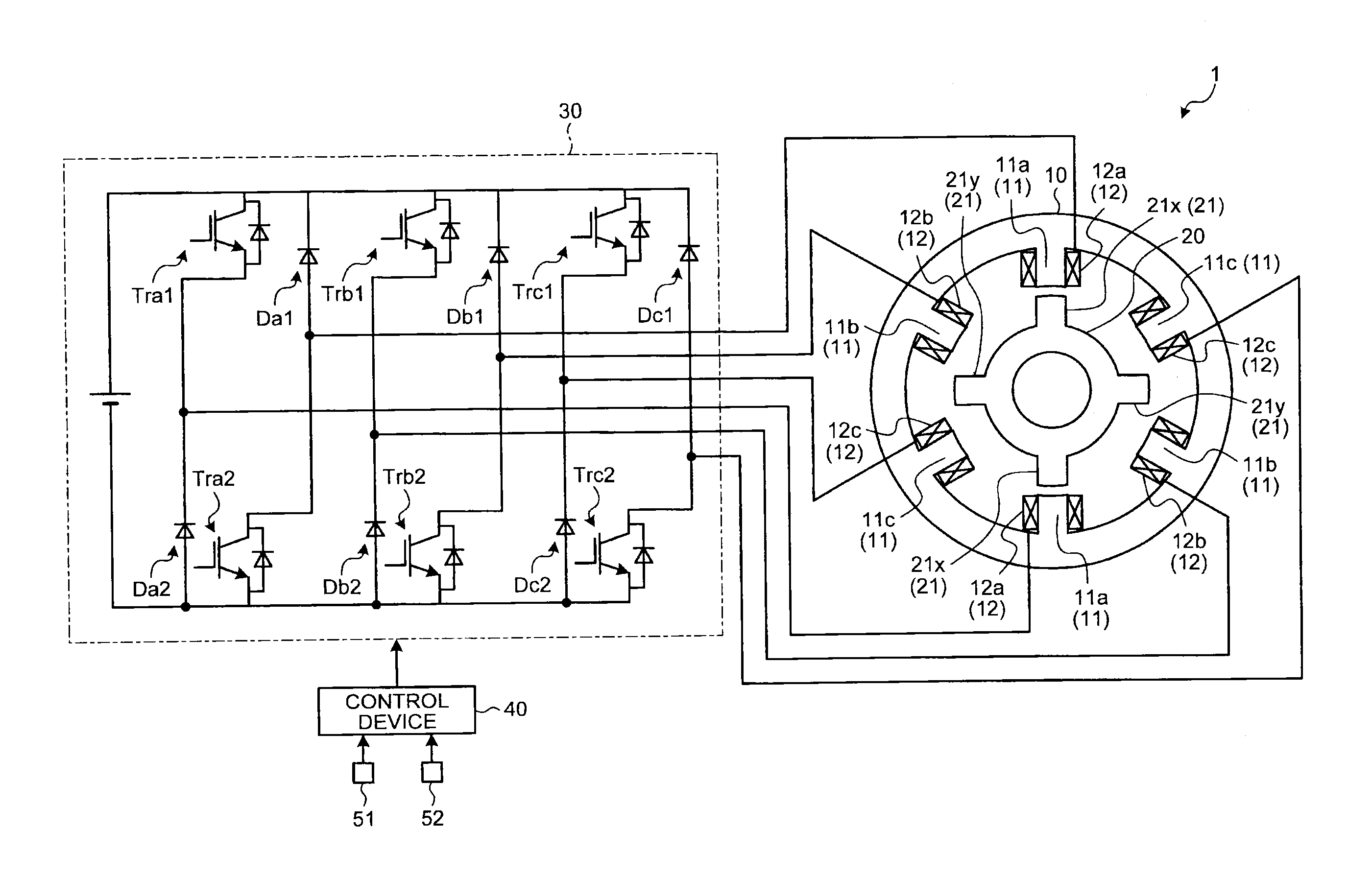
[0032]A switched reluctance motor (hereinafter, referred to as “SR motor”) 1 of this embodiment is provided with a stator 10, a rotor 20, a driving circuit 30, and a control device 40 as illustrated in FIG. 1.

[0033]The stator 10 is provided with a plurality of stator teeth 11 as salient poles in a radial fashion on an annular inner peripheral surface. The stator 10 is provided with a plurality of pairs of stator teeth 11 opposed to each other in a radial direction. In the SR motor 1, a pair of stator teeth 11 forms one phase. Furthermore, each stator tooth 11 includes concentrically wound winding wire 12.

[0034]The rotor 20 is arranged on an inner ...


PUM


Abstract

A switched reluctance motor includes: a stator provided with a plurality of stator teeth as salient poles in a radial fashion with winding wire wound around each of the plurality of stator teeth; a rotor provided with a plurality of rotor teeth as salient poles in a radial fashion; a driving circuit configured to apply a current to the winding wire for each phase; and a control device configured to control the driving circuit, the control device being configured to perform: starting rising of a current to the winding wire of a stator tooth of a phase being a non-excitation target due to stop of energization to the winding wire; and allowing the current applied to the winding wire of the stator tooth of a phase being an excitation target to fall.

Description

CROSS-REFERENCE TO RELATED APPLICATION(S)[0001]The present application claims priority to and incorporates by reference the entire contents of Japanese Patent Application No. 2014-163909 filed in Japan on Aug. 11, 2014.BACKGROUND OF THE INVENTION[0002]1. Field of the Invention[0003]The present invention relates to a switched reluctance motor.[0004]2. Description of the Related Art[0005]A switched reluctance motor including a stator and a rotor each of which is provided with a plurality of salient poles which might be opposed to each other and winding wire wound around the salient pole of the stator is conventionally known. The switched reluctance motor is configured to realize rotational movement of the rotor by magnetic attractive force generated between the salient poles of the stator and the rotor. The switched reluctance motor is disclosed in Japanese Patent Application Laid-open No. 8-205581. The switched reluctance motor of Japanese Patent Application Laid-open No. 8-205581 ob...

Claims


Application Information

Patent Timeline
IPC IPC(8): H02P25/08
CPCH02P25/085H02P25/082H02P25/092H02P25/08H02P25/0925H02P25/086
Inventor DEGUCHI, JUN-ICHIARAKAWA, KAZUYAYOSHIZUE, KENSUKEHOSHI, NOBUKAZUNAKAYAMA, NOBORUIGUCHI, TAKUYA
Owner TOYOTA JIDOSHA KK
Why Eureka
Try Eureka