
Display device

a display device and display screen technology, applied in non-linear optics, instruments, optics, etc., can solve the problems of deteriorating light extraction efficiency and reducing light extraction efficiency, and achieve excellent color reproduction, improved viewing angle, and improved light extraction efficiency.

Active Publication Date: 2016-02-11
SAMSUNG DISPLAY CO LTD
View PDF6 Cites 50 Cited by
  • Summary
  • Abstract
  • Description
  • Claims
  • Application Information

AI Technical Summary

Benefits of technology

The invention improves how much light a display device can catch by reducing the amount of light that gets reflected back to the device from the air above it. This makes the light more likely to escape from the device and be seen by the user.

Problems solved by technology

In a case where the color conversion layer including the phosphor is used in an upper substrate, the LCD device may have an improved viewing angle and excellent color reproduction, but light extraction efficiency may deteriorate.
Light converted inside the color conversion layer may be trapped in a resin and the like inside the color conversion layer or may not escape from the upper substrate due to total internal reflection that occurs at a boundary between the external air and the upper substrate, which results in a decrease in the light extraction efficiency.

Method used


Image

  • Display device
  • Display device
  • Display device

Examples


first embodiment

[0051]Hereinafter, a display device according to the present invention will be described with reference to FIGS. 1 to 3.

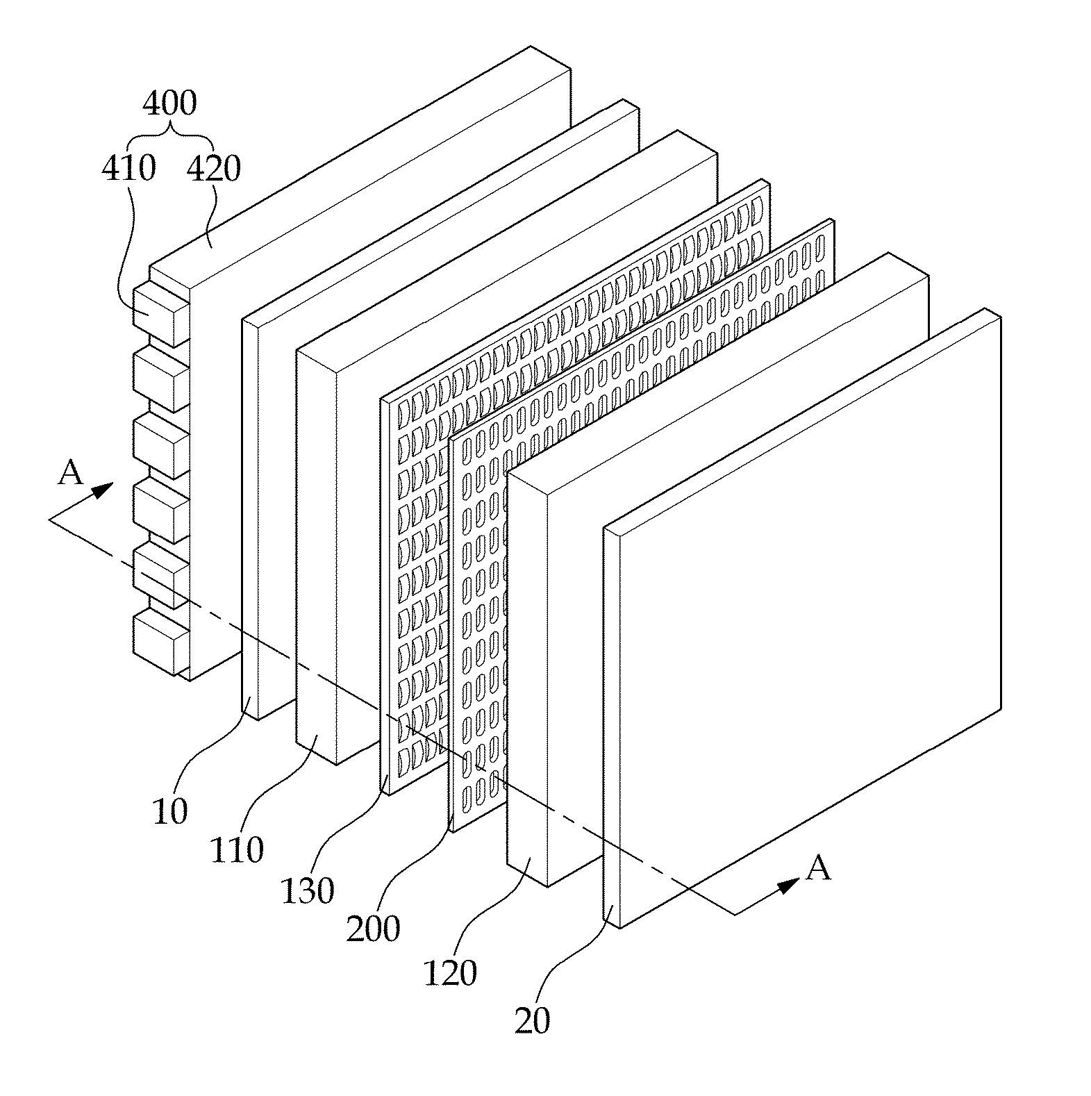
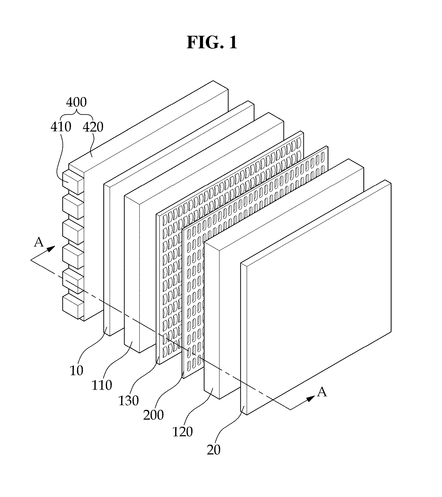
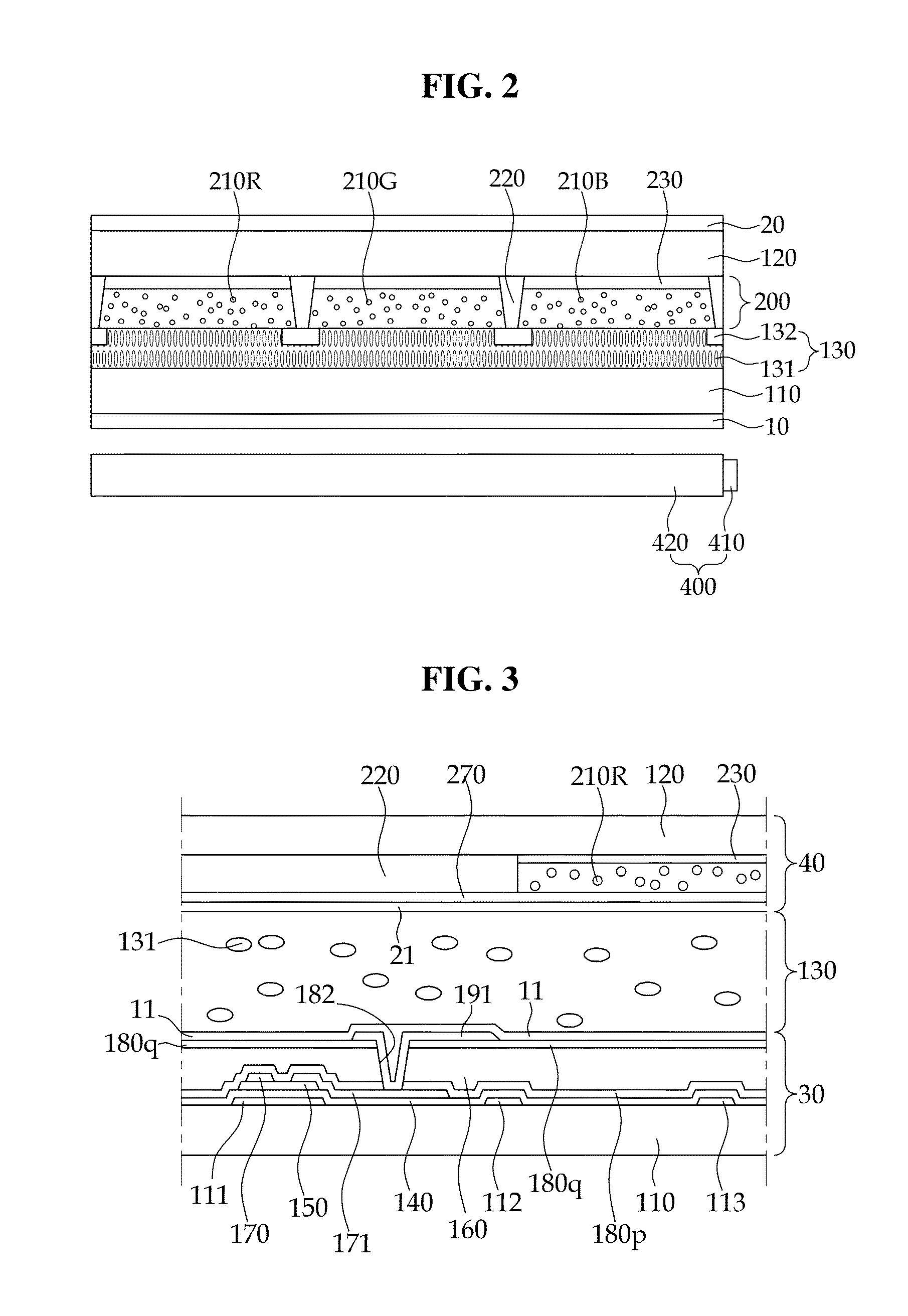
[0052]FIG. 1 is an exploded perspective view illustrating a display device according to a first embodiment of the present invention. FIG. 2 is a schematic cross-sectional view along A-A illustrating the display device of FIG. 1. FIG. 3 is a cross-sectional view illustrating one pixel of the display device of FIG. 2. FIG. 4 is a cross-sectional view illustrating that light passing through an air layer is extracted to the outside. FIG. 5 is a graph illustrating light extraction efficiency when the air layer is applied.

[0053]Referring to FIGS. 1 to 3, the display device includes a first substrate 110, a light-amount adjusting layer 130 disposed on the first substrate 110, a second substrate 120 disposed on the light-amount adjusting layer 130 and facing the first substrate 110, a backlight unit 400 disposed under the first substrate 110, a first polarizer 10 disposed ...

second embodiment

[0120]Referring to FIG. 8, the display device according to the present invention includes a low-refractive index layer 240 instead of the air layer. The air layer is a medium that has a low refractive index compared to the second substrate 120 or the phosphor, and thus the low-refractive index layer 240 that can bring about a similar effect as the air layer can be used.

[0121]The low-refractive index layer 240 includes aerogel. The aerogel has a refractive index in a range of 1.007 to 1.05. That is, the aerogel has a refractive index substantially similar to the air. Therefore, the low-refractive index layer 240 may produce an effect substantially the same as the air layer.

[0122]The aerogel has a structure where SiO2 nanostructures having a thickness of a ten thousandth of a human hair are extremely loosely tangled and air molecules may account for 90% or more of the whole volume in the nanostructure. The aerogel may be manufactured by the following processes: a wet-gel manufacturing...

third embodiment

[0123]Referring to FIG. 9, the display device according to the present invention includes a pattern 250 on the air layer. In a case where the pattern 250 is disposed on the air layer, light scattering may occur more actively inside the air layer. Therefore, the light extraction efficiency of the display device is improved.


PUM

PropertyMeasurementUnit
diameteraaaaaaaaaa
diameteraaaaaaaaaa
diameteraaaaaaaaaa

Abstract

A display device includes: a first substrate; a second substrate facing the first substrate; a light-amount adjusting layer interposed between the first substrate and the second substrate; and a backlight unit disposed under the first substrate, wherein the second substrate includes a plurality of color conversion layers respectively disposed on a plurality of pixel regions, the color conversion layer includes a partition wall; and a phosphor disposed on areas defined by the partition wall, and the color conversion layer includes an air layer between the second substrate and the phosphor.

Description

CLAIM OF PRIORITY[0001]This application claims the priority to and all the benefits accruing under 35 U.S.C. §119 of Korean Patent Application No. 10-2014-0100602, filed on Aug. 5, 2014, with the Korean Intellectual Property Office (“KIPO”), the disclosure of which is incorporated herein in its entirety by reference.BACKGROUND OF THE INVENTION[0002]1. Field of the Invention[0003]The present disclosure of invention relates to a display device that includes a color conversion layer including an air layer configured to improve light extraction efficiency.[0004]2. Description of the Related Art[0005]A liquid crystal display (LCD) is a type of flat panel displays (FPDs), which is the most widely used these days. The LCD includes two substrates including electrodes formed thereon and a liquid crystal layer interposed therebetween. Upon applying voltage to the electrodes, liquid crystal molecules of the liquid crystal layer are rearranged, thereby adjusting the amount of transmitted light....

Claims


Application Information

Patent Timeline
Patent Type & Authority Applications(United States)
IPC IPC(8): G02F1/1335
CPCG02F1/133617G02F2001/133614G02F1/133553G02F1/133528G02F2203/023G02F1/133514G02F1/133614
Inventor LEE, KWANG KEUNKWON, JUNG HYUNYOON, SEON TAEPARK, HAE IL
Owner SAMSUNG DISPLAY CO LTD
Learn More