
Vehicle lower section structure

a lower section and vehicle technology, applied in the direction of roofs, transportation and packaging, vehicle arrangements, etc., can solve the problems of ineffective transmission of collision load from side members to floor panels, and ineffective load transmission with the floor tunnel, so as to reduce weight and raise cross-sectional rigidity

Inactive Publication Date: 2016-02-11
TOYOTA JIDOSHA KK
View PDF0 Cites 30 Cited by
  • Summary
  • Abstract
  • Description
  • Claims
  • Application Information

AI Technical Summary

Benefits of technology

The vehicle lower section structure described in this patent can effectively transmit loads in an oblique collision, preventing deformation of the tunnel section. It can also increase rigidity while reducing weight.

Problems solved by technology

In such cases, there is a possibility in the above structure that the collision load is not transmitted effectively from the side member to the floor panel, due the side member and the floor panel not being directly connected to each other.
However, due to the reinforcement plate being configured by a rectangular shape formed with plural triangular holes, the possibility arises that effective load transmission with the floor tunnel will not be achieved in cases in which a large collision load has been transmitted to the floor panel.

Method used


Image

  • Vehicle lower section structure
  • Vehicle lower section structure
  • Vehicle lower section structure

Examples


Embodiment Construction

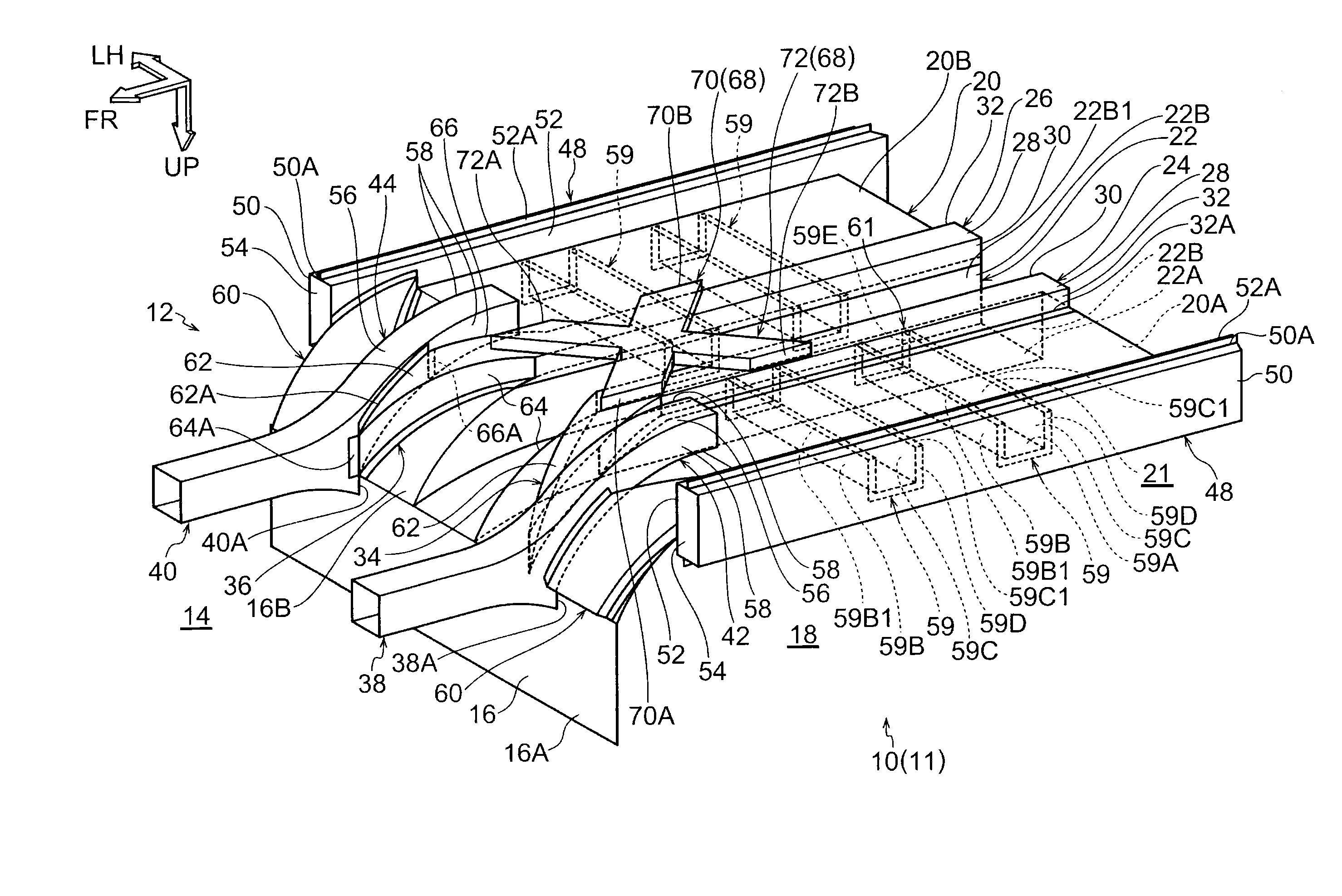
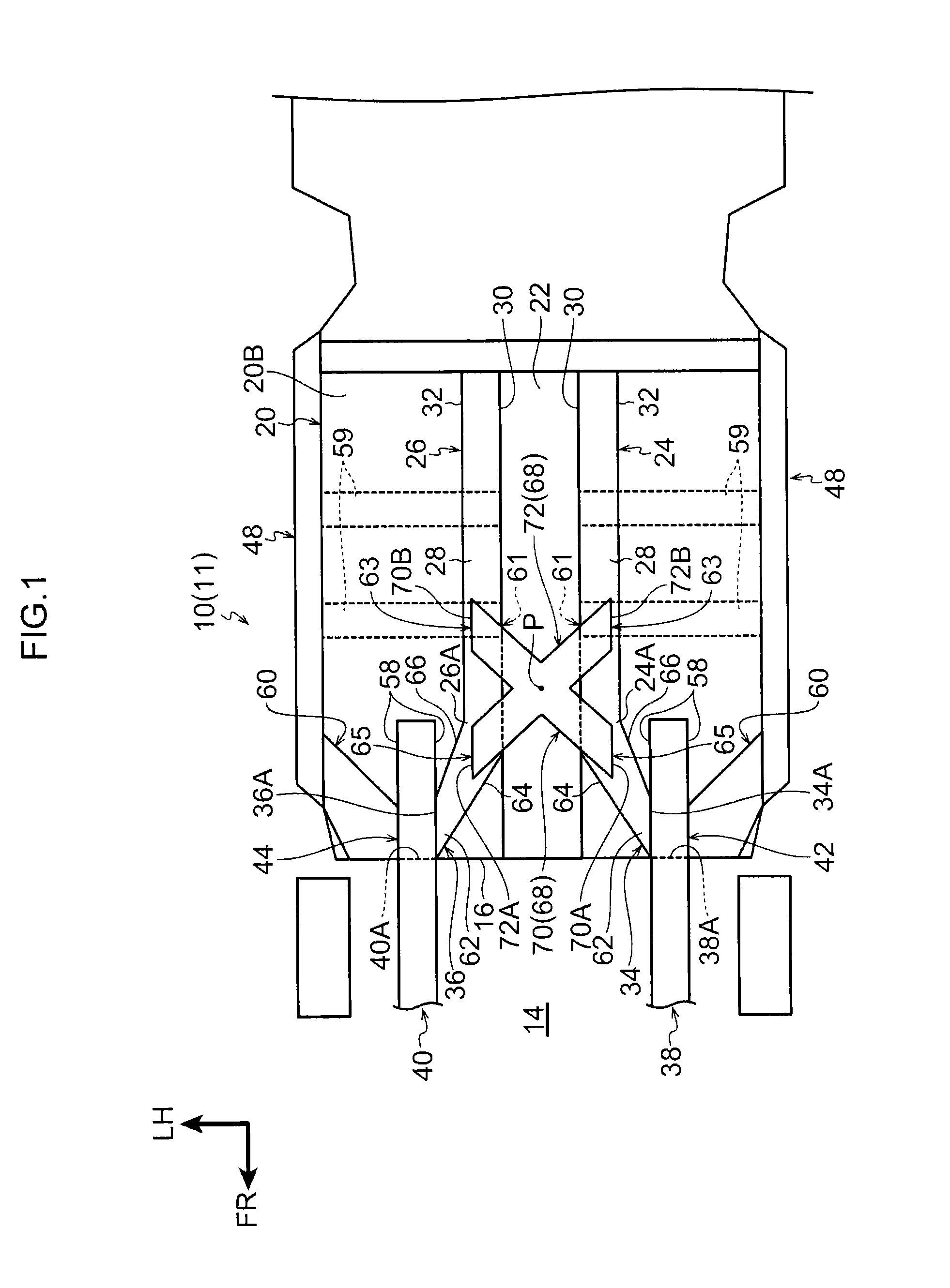
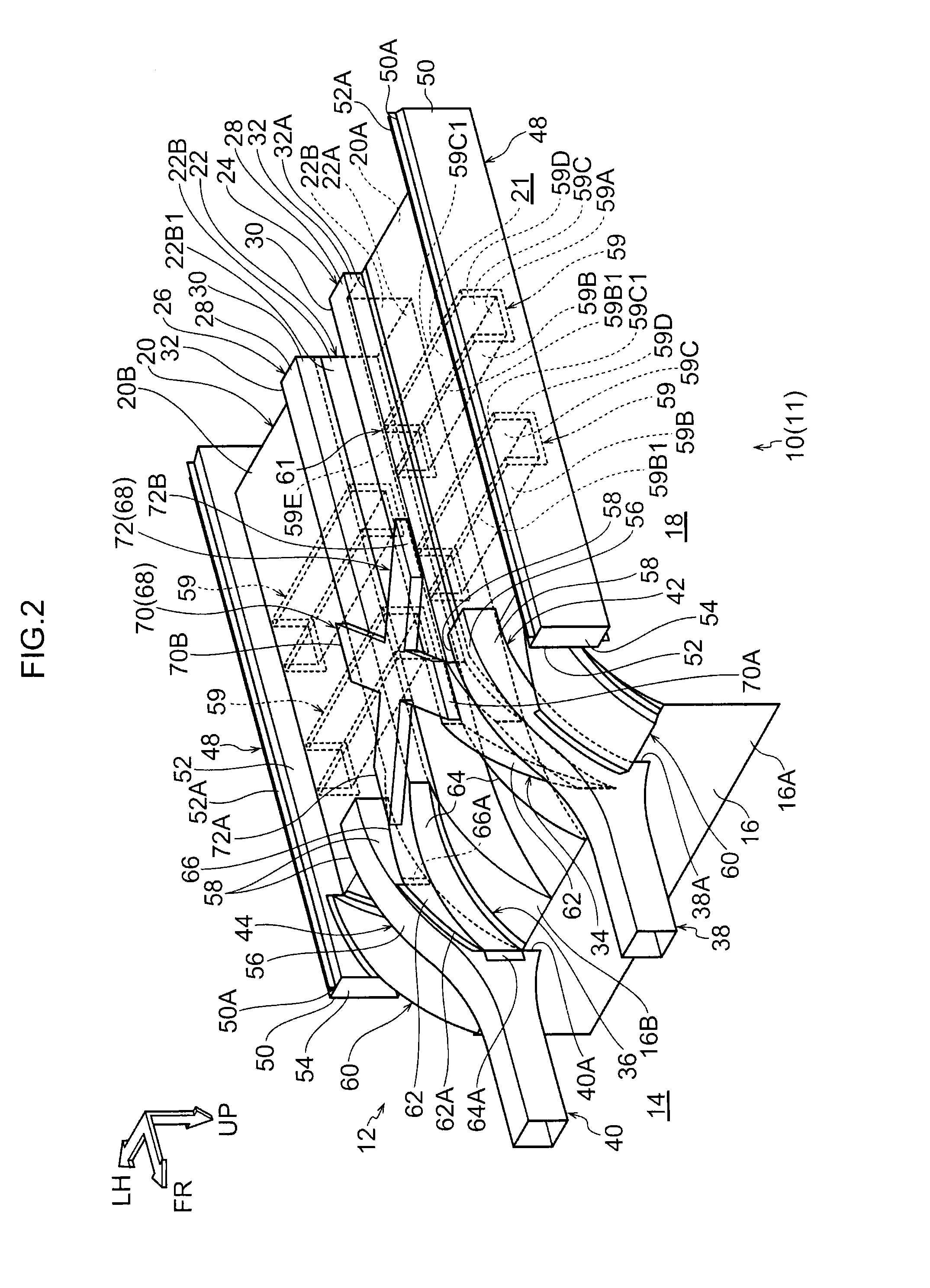
[0048]Explanation follows regarding a vehicle lower section structure according to an exemplary embodiment, with reference to the drawings. In each of the drawings, arrow FR, arrow UP, arrow RH, and arrow LH indicate, as appropriate, the front direction, up direction, right direction, and left direction of a vehicle applied with a vehicle lower section structure 10 according to the present exemplary embodiment. In the following, simple reference to directions front-rear, up-down, and left-right indicate front-rear in the vehicle front-rear direction, up-down in the vehicle up-down direction, and left-right direction when facing forwards, unless stated otherwise.

[0049]Explanation first follows regarding a configuration of a vehicle lower section structure according to the present exemplary embodiment. FIG. 1 illustrates a bottom view of the vehicle lower section structure 10 according to the present exemplary embodiment, and FIG. 2 illustrates a perspective view of the vehicle lower ...


PUM


Abstract

The present disclosure relates to a vehicle lower section structure that may obtain efficient load transmission obliquely toward the rear side, even in the event of an oblique collision. A reinforcement member is coupled to one lower tunnel reinforcement, and is coupled to another a lower tunnel reinforcement on progression toward the rear side. Collision load transmitted to the reinforcement member is accordingly transmitted obliquely toward the rear from the one lower tunnel reinforcement to the other lower tunnel reinforcement. Namely, the vehicle lower section structure of the present disclosure is capable of obtaining effective load transmission obliquely toward the rear side even in the event of an oblique collision.

Description

CROSS-REFERENCE TO RELATED APPLICATION[0001]This application claims priority under 35 USC 119 from Japanese Patent Application No. 2014-159668, filed on Aug. 5, 2014, the disclosure of which is incorporated by reference herein.BACKGROUND OF THE INVENTION[0002]1. Field of the Invention[0003]The present disclosure relates to a vehicle lower section structure.[0004]2. Description of the Related Art[0005]Technology is described in Japanese Patent Application Laid-Open (JP-A) No. H06-144300 that includes a floor panel (tunnel section) extending along the vehicle front-rear direction at a central portion in the vehicle width direction of a front floor (floor), and a rectangular shaped reinforcement plate formed with plural triangular shaped holes in an up-down direction central portion of a front end section side of the floor panel.[0006]For example, in an oblique collision from the vehicle width direction outer side of a side member, a large collision load is input from the side member a...

Claims


Application Information

Patent Timeline
IPC IPC(8): B62D21/15B62D21/06B62D21/08B62D25/20
CPCB62D21/155B62D21/06B62D25/20B62D21/08B62D21/15B62D25/2018B62D25/2036
Inventor TAKENAKA, SUSUMU
Owner TOYOTA JIDOSHA KK
Learn More