Liquid cartridge
a liquid cartridge and liquid technology, applied in printing and other directions, can solve the problems of known ink jet recording apparatus not being able to estimate the viscosity of ink stored in an ink container, etc., and achieve the effect of estimating the viscosity of liquid stored in the liquid chamber
- Summary
- Abstract
- Description
- Claims
- Application Information
AI Technical Summary
Benefits of technology
Problems solved by technology
Method used
Image
Examples
first modified embodiment
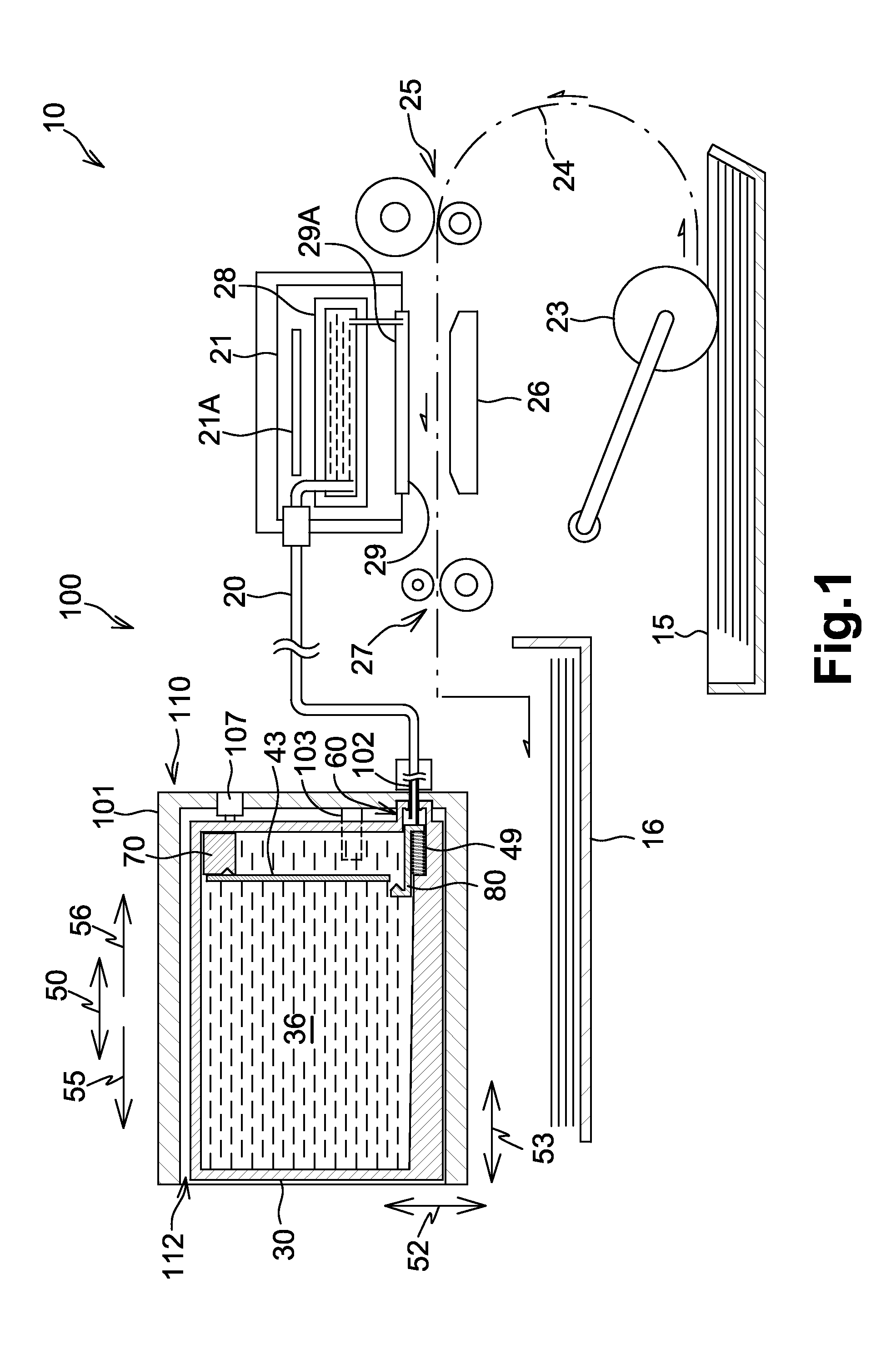
[0100]Referring to FIG. 9, an ink cartridge 30 according to a first modified embodiment is described. The descriptions of the parts which are common between the above-described embodiment and the first modified embodiment may be omitted, but the parts of the first modified embodiment which are different from the parts of the above-described embodiment are described. Similarly, the descriptions of the parts which are common among the above-described embodiment, the first modified embodiment, and the later-described further modified embodiments may be omitted if they are once described. Moreover, the parts of the above-described embodiment, the first modified embodiment, and the later-described further modified embodiments can be arbitrarily combined as long as the object of the invention is achieved.
[0101]In the ink cartridge 30 according to the first modified embodiment, the movable member (float, detection portion, light blocking portion) 70 is connected to the restriction portion ...
second modified embodiment
[0103]Referring to FIGS. 10A and 10B, an ink cartridge 30 and a cartridge mounting portion 110 according to a second modified embodiment are described. The controller 130 determines that the movable member (float, detection portion, light blocking portion) 70 is released from the restriction portion 81 when the mount sensor 107 outputs the signal indicating that the ink cartridge 30 is in the mount position. In other words, the controller 130 determines that the movable member (float, detection portion, light blocking portion) 70 is released from the restriction portion 81 at a timing when the detection signal output from the mount sensor 107 changes from the signal indicating that the ink cartridge 30 is not in the mount position to the signal indicating that the ink cartridge 30 is in the mount position.
[0104]The timing when the movable member (float, detection portion, light blocking portion) 70 is released from the restriction portion 81 and the timing when the mount sensor 107 ...
third modified embodiment
[0108]Referring to FIGS. 11A and 11B, an ink cartridge 30 and a cartridge mounting portion 110 according to a third modified embodiment are described. The restriction member of the ink cartridge 30 comprises a gas bag 85 positioned in the front wall 40. The gas bag 85 is penetrated through the front wall 40 in the depth direction 53. The gas bag 85 is filled with gas and bulges into the ink chamber 36. The state of the gas bag 85 is called a bulging state. The gas bag 85 in the bulging state contacts the upper end of the movable member (float, detection portion, light blocking portion) 70 and thereby functions as a restriction member restricting the movement of the movable member (float, detection portion, light blocking portion) 70. The restriction portion 81 and the connection portion 83 are omitted in the ink cartridge 30 according to the third modified embodiment, and the operation portion 82 is replaced with a valve configured to selectively open and close the ink supply openin...
PUM
 Abstract
Description
Claims
Application Information
 - R&D
- Intellectual Property
- Life Sciences
- Materials
- Tech Scout
- Unparalleled Data Quality
- Higher Quality Content
- 60% Fewer Hallucinations
Browse by: Latest US Patents, China's latest patents, Technical Efficacy Thesaurus, Application Domain, Technology Topic, Popular Technical Reports.
© 2025 PatSnap. All rights reserved.Legal|Privacy policy|Modern Slavery Act Transparency Statement|Sitemap|About US| Contact US: help@patsnap.com


