Light source device

a light source and light source technology, applied in the direction of illuminated signs, display means, instruments, etc., can solve the problems of unevenness in the chromaticity distribution, the difference between the directivities of both light sources, and the difficulty of matching the brightness distribution and the chromaticity distribution, etc., to achieve unevenness easily

Inactive Publication Date: 2016-02-04
CANON KK
View PDF1 Cites 1 Cited by
  • Summary
  • Abstract
  • Description
  • Claims
  • Application Information

AI Technical Summary

Benefits of technology

[0006]However, when the local diming control is performed in the light source device including both of the LEDs and the laser diodes, a difference between directivities of both the light sources is a problem. This problem means that it is extremely difficult to match a brightness distribution and a chromaticity distribution because, in most of the LEDs, a half-value angle of the directivity is 120 degrees and, on the other hand, in the laser diodes, a half-value angle of the directivity is approximately 0 degrees to 30 degrees. Because of this problem, when the LEDs and the laser diodes are lit at different brightness for each of the divided regions by the local dimming control, unevenness easily occurs in the chromaticity distribution.

Problems solved by technology

However, when the local diming control is performed in the light source device including both of the LEDs and the laser diodes, a difference between directivities of both the light sources is a problem.
This problem means that it is extremely difficult to match a brightness distribution and a chromaticity distribution because, in most of the LEDs, a half-value angle of the directivity is 120 degrees and, on the other hand, in the laser diodes, a half-value angle of the directivity is approximately 0 degrees to 30 degrees.
Because of this problem, when the LEDs and the laser diodes are lit at different brightness for each of the divided regions by the local dimming control, unevenness easily occurs in the chromaticity distribution.

Method used


Image

  • Light source device
  • Light source device
  • Light source device

Examples


first embodiment

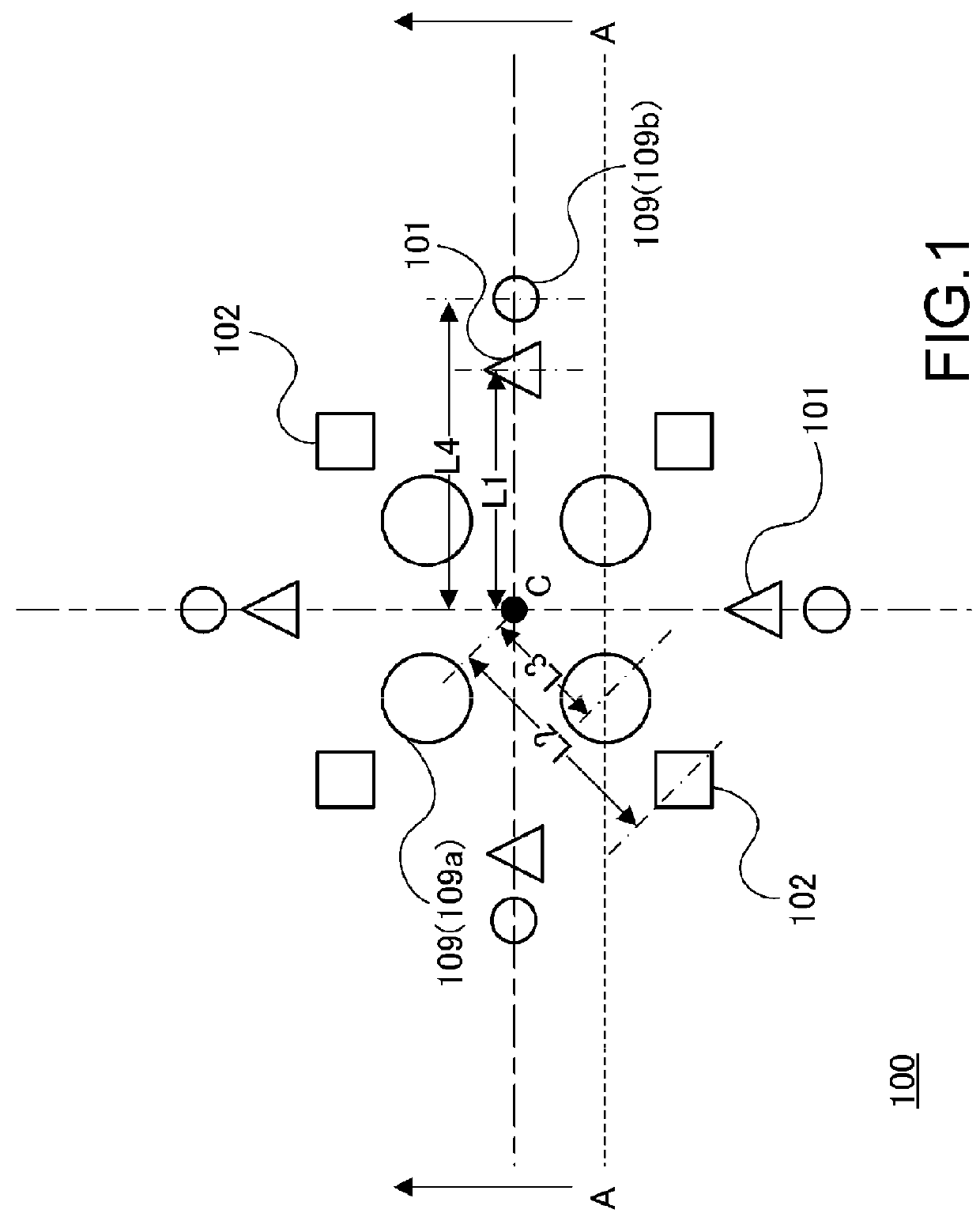
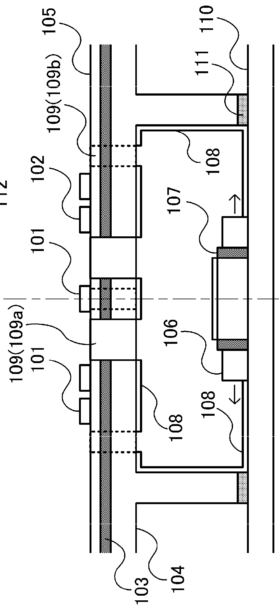
[0016]A light source device according to a first embodiment of the present invention is explained.

[0017]The light source device according to this embodiment is a light source device in which local dimming control can be performed. The light source device includes a plurality of divided regions (light emitting blocks) in which light emission brightness can be individually changed. With one or more divided regions set as one light emission unit, the light source device is configured to be capable of emitting light at determined light emission brightness for each light emission unit. The light source device according to this embodiment can be used as, for example, a backlight device for a liquid crystal display apparatus. Note that the present invention can be suitably applied to not only the backlight device but also, for example, a light source device of a display apparatus (an advertisement sign apparatus, a sign display apparatus, etc.) that transmits light and displays an image. T...

second embodiment

[0058]A light source device 200 according to a second embodiment of the present invention is explained below.

[0059]In the first embodiment explained above, the configuration is explained in which the reflecting sections 108 and the light-transmitting hole sections 109 are set as the diffusing structure for diffusing the light of the light source 106 and reflecting the light to the diffusing section 112 side.

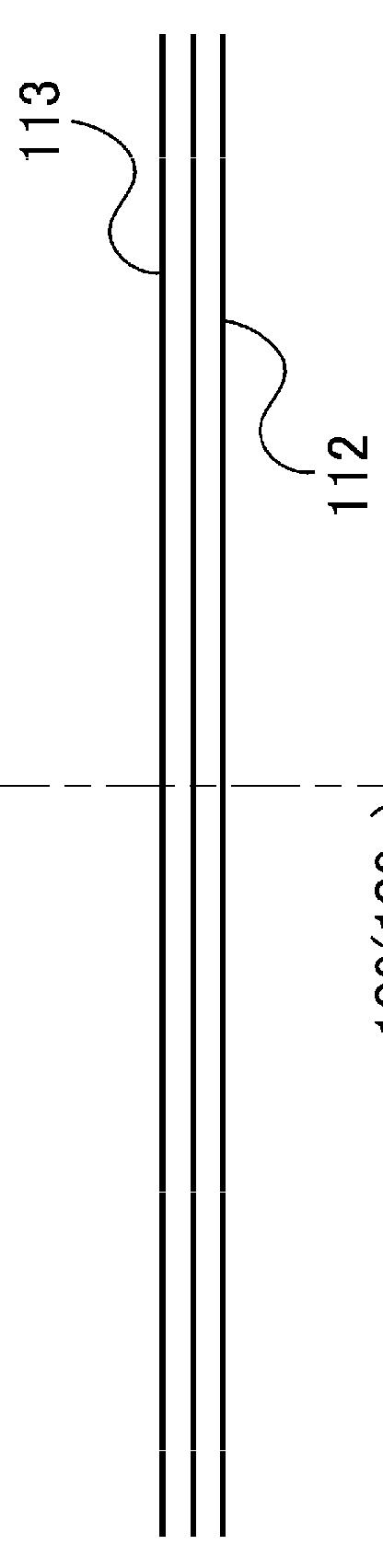
[0060]On the other hand, in this embodiment, a configuration is explained in which a light guide plate is added to the configuration in the first embodiment as a structure for diffusing light of the light source 106. Note that, in this embodiment, components different from the components in the first embodiment are explained. Explanation of components same as the components in the first embodiment is omitted.

[0061]FIG. 4 is a diagram showing the schematic configuration of a main part of the light source device 200 according to this embodiment and is a sectional view of one lighti...


PUM

PropertyMeasurementUnit
widthaaaaaaaaaa
half-value angleaaaaaaaaaa

Abstract

A light source device comprises a plurality of kinds of light sources having different directivity characteristics and including a first light source and a second light source having a directivity characteristic wider than a directivity characteristic of the first light source; and a diffusing structure section for radiating light emitted by the first light source after diffusing the light, wherein a position of a center of a first brightness distribution of light radiated from the diffusing structure section in a case when the first light source emits light is a position corresponding to a position of a center of a second brightness distribution in a case when the second light source emits light.

Description

BACKGROUND OF THE INVENTION[0001]1. Field of the Invention[0002]The present invention relates to a light source device.[0003]2. Description of the Related Art[0004]In a light source device, in particular, a backlight device for a liquid crystal display apparatus, there is a method of realizing a wide color gamut corresponding to a display color of a video signal using a structure obtained by combining light emitting diodes (hereinafter, LEDs) of red, green, and blue. However, in the case of the backlight device for the liquid crystal display apparatus including the LEDs of red, green, and blue, there is a limit in expansion of a display color gamut because of a relation between spectral characteristics of the LEDs and transmission characteristics of a liquid crystal display panel. For example, when all of the LEDs of red, green, and blue of the backlight device are lit and only a green color filter of the liquid crystal display panel is set to transmit light, components of red and b...

Claims


Application Information

Patent Timeline
Patent Type & Authority Applications(United States)
IPC IPC(8): F21V3/04G02F1/1335
CPCG02F1/133606F21V3/049G02F1/133603G02F1/133628
Inventor MATSUURA, YASUHIRO
Owner CANON KK
Why Eureka
Try Eureka