
Devices and methods for treating heart failure

a heart failure and heart failure technology, applied in the field of heart failure treatment, can solve the problems of reduced cardiac output, inadequate blood to meet the needs of body tissues, little survival effect, calcium overload,

Active Publication Date: 2016-01-28
CORVIA MEDICAL
View PDF1 Cites 118 Cited by
  • Summary
  • Abstract
  • Description
  • Claims
  • Application Information

AI Technical Summary

Benefits of technology

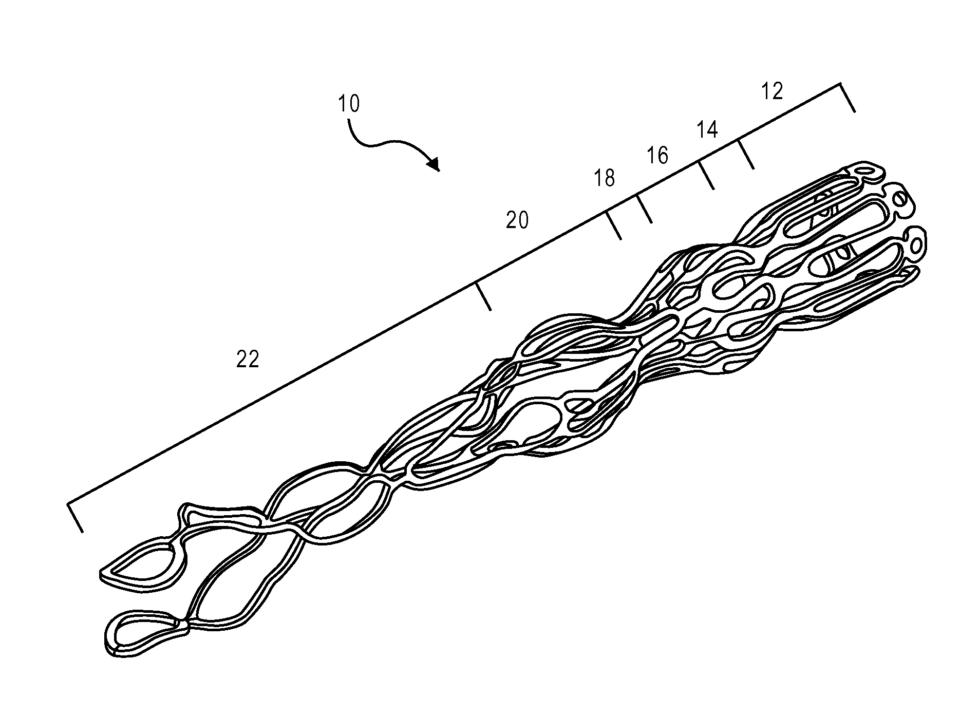
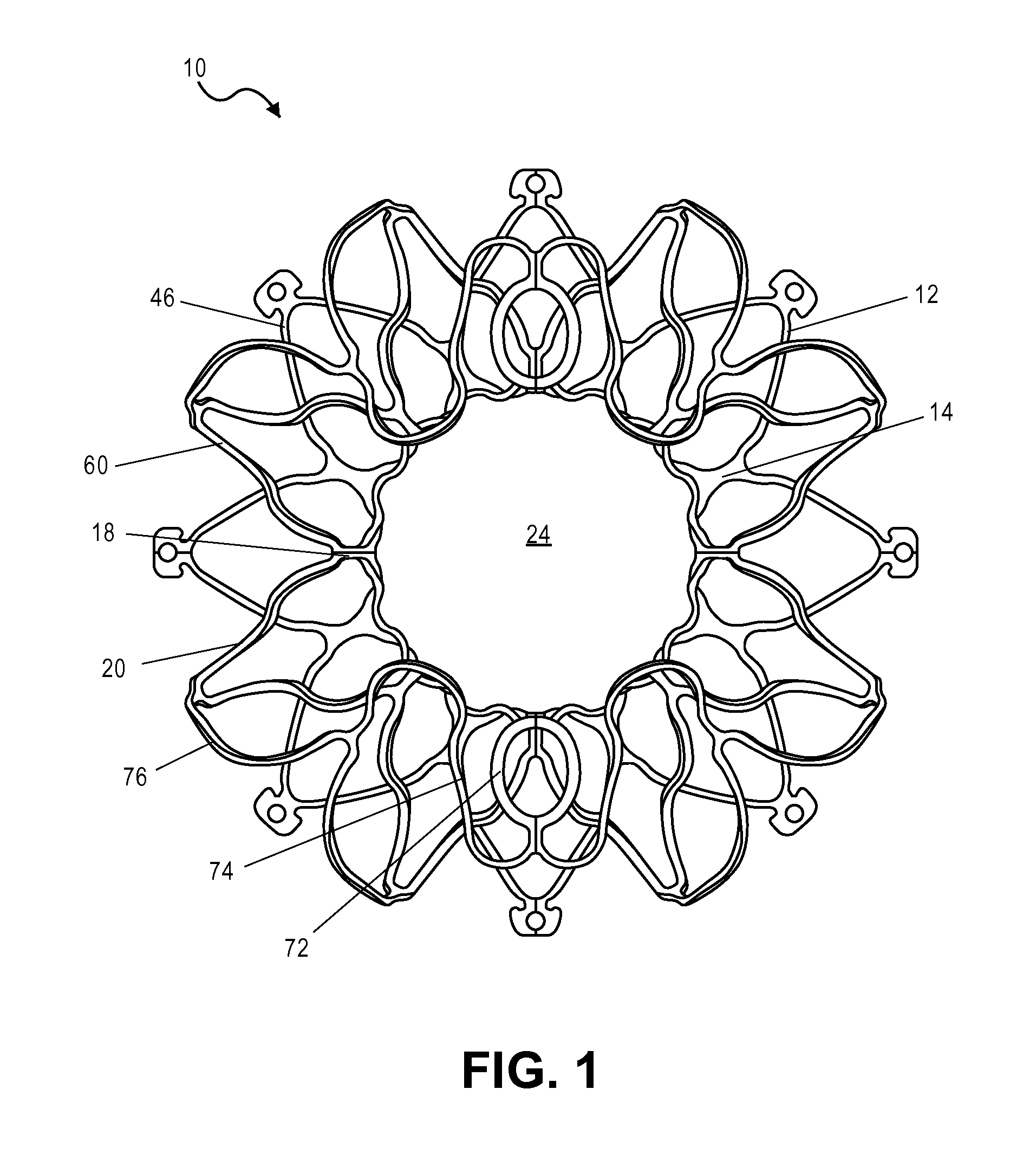
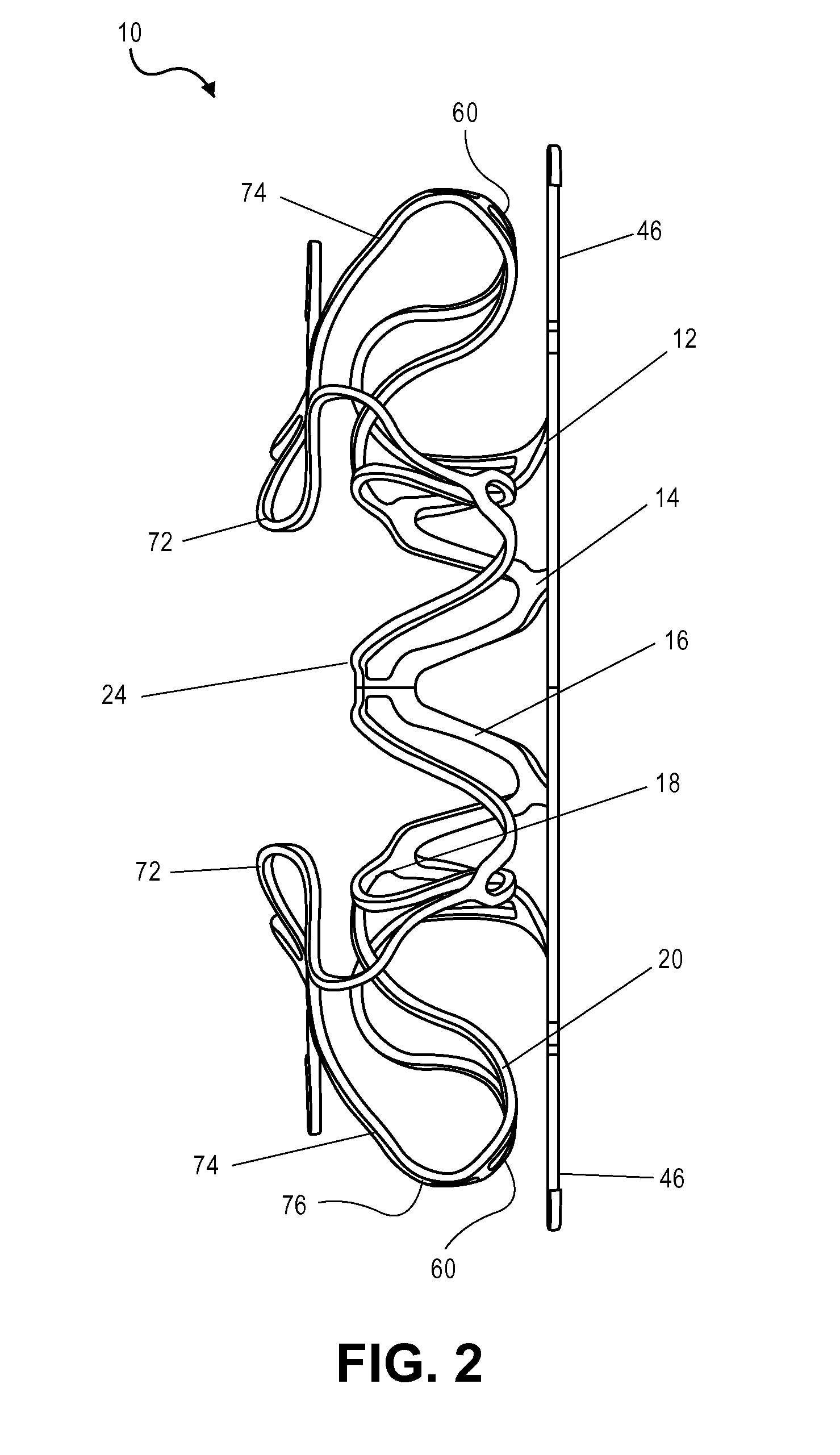
The invention is about a device and method for implanting a cardiac pressure relief device in the heart. The device has a core region with retention segments that can be expanded from a collapsed delivery configuration to a deployed configuration. The device also has a distal retention region, a proximal retention region, and a retrieval region with retrieval members that can be expanded from a collapsed delivery configuration to a deployed configuration. The device can be easily observed and the attachment elements can move out of the way to allow for easy retrieval. The method includes expanding the retention regions and releasing the retrieval members from the delivery system. The device and method provide improved flexibility and maneuverability during implantation and retrieval.

Problems solved by technology

CHF causes a reduced cardiac output and inadequate blood to meet the needs of body tissues.
While pharmacological treatments can improve quality of life, they have little effect on survival.
However, in a chronic ischemic heart, high-rate pacing may lead to an increased diastolic pressure, calcium overload, and damages to the muscle fibers.
These surgical treatments are invasive and have many limitations.
Generally, DHF is a failure of the ventricle to adequately relax and expand, resulting in a decrease in the stroke volume of the heart.
Presently, there are very few treatment options for patients suffering from DHF.

Method used


Image

  • Devices and methods for treating heart failure
  • Devices and methods for treating heart failure
  • Devices and methods for treating heart failure

Examples


Embodiment Construction

[0036]The present teachings are described more fully herein with references to the accompanying drawings, which show certain embodiments of the present teachings. The present teachings may, however, be embodied in many different forms and should not be construed as being limited to the embodiments set forth herein. Rather, these embodiments are provided to illustrate various aspects of the present teachings. Like numbers refer to like elements throughout.

[0037]The present teachings provide a device and methods of use thereof. For example, the device can be used to regulate the pressure in a heart chamber. Specifically, the device can be used to (a) change an elevated chamber pressure and (b) prevent embolization from the right to left atria in a patient who suffers from CHF or has a Patent Foramen Ovale (PFO) or an Atrial Septal Defect (ASD) but needs a residual flow between the atria so as not to traumatize the heart hemodynamics.

[0038]As used herein, when terms “distal” and “proxi...


PUM


Abstract

A device for implanting into an atrial septum of a patient. In some embodiments, the device has a core region to be disposed in an opening in the atrial septum; a distal retention region adapted to engage tissue on a left atrial side of the septal wall; a proximal retention region adapted to engage tissue on a right atrial side of the septal wall; and a retrieval region comprising a plurality of retrieval members, each retrieval member comprising a connector at a proximal end, the connector being adapted to connect to a delivery system. The device has a delivery configuration and a deployed configuration, the core region, distal retention region and proximal retention region each having a smaller diameter in the delivery configuration than in the deployed configuration, the retrieval member connectors being disposed proximal to and radially outward from the opening in the deployed configuration.

Description

CROSS REFERENCE TO RELATED APPLICATIONS[0001]This application claims the benefit under 35 U.S.C. §119 of U.S. Patent Appl. No. 62 / 028,286, filed Jul. 23, 2014, and U.S. Patent Appl. No. 62 / 167,624, filed May 28, 2015, the disclosures of which are incorporated by reference.INCORPORATION BY REFERENCE[0002]All publications and patent applications mentioned in this specification are incorporated herein by reference in their entirety to the same extent as if each individual publication or patent application was specifically and individually indicated to be incorporated by reference.FIELD[0003]The present teachings relate to devices and methods of use thereof for treating heart failures. An aspect of the present teachings relates to a device that can be used to change (e.g., reduce) the blood pressure in a heart chamber, for example, by creating a shunt, and optionally regulating the flow of blood through the shunt in order to enhance the therapeutic effect of the shunt. The present teach...

Claims


Application Information

Patent Timeline
Patent Type & Authority Applications(United States)
IPC IPC(8): A61M27/00A61F2/24
CPCA61M27/002A61F2/24A61F2/2478A61M2205/04A61F2002/249A61M2210/125A61F2/0063A61F2002/0072A61B17/0218A61B17/11A61B2017/00252A61B2017/00606A61B2017/00623A61B2090/3966A61B2017/00575A61B2017/00592A61B2017/00601
Inventor FORCUCCI, STEPHEN J.FINCH, MATTHEW J.MAGNIN, CHRISTOPHER J.MCNAMARA, EDWARD I.DEVELLIAN, CAROL A.
Owner CORVIA MEDICAL
Learn More