
Coil systems for magnetic resonance imaging

a coil system and magnetic resonance imaging technology, applied in the field of coil systems for magnetic resonance imaging, can solve the problems of decreased sensitivity, reduced image quality, additional discomfort of patients, etc., and achieve the effect of increasing the number of axial slices obtained by the coil system, and increasing the overall imaging tim

Active Publication Date: 2016-01-28
INVIVO CORP
View PDF6 Cites 17 Cited by
  • Summary
  • Abstract
  • Description
  • Claims
  • Application Information

AI Technical Summary

Benefits of technology

This patent describes a new way to compress and image the breast using a special coil system in the MRI machine. By positioning the coils in the X-Y plane and compressing the breast in the cranio-caudal direction, the number of axial slices required is decreased, resulting in faster throughput without sacrificing imaging quality. The compression is gentle, improving patient comfort. The coil system uses butterfly coils, which create flux lines linking the two fields in-between the two loops to detect the magnetic resonance signals. This approach provides improved sensitivity and can detect the magnetic resonance signals without the need for additional sensitivity pads.

Problems solved by technology

Because the imaging compressing systems used in the MRI imaging procedure are typically uncomfortable for the patient, the increase in the overall imaging time can cause the patient additional discomfort.
In addition, with the previously described left to right compression, the axial slices can decrease in sensitivity and result in images of lower quality.
For typical lateral compression, using butterfly or microstrip coils is not as attractive because these types of coils are not as sensitive as circular surface coils for use in cranio-caudal compression.

Method used


Image

  • Coil systems for magnetic resonance imaging
  • Coil systems for magnetic resonance imaging
  • Coil systems for magnetic resonance imaging

Examples


Embodiment Construction

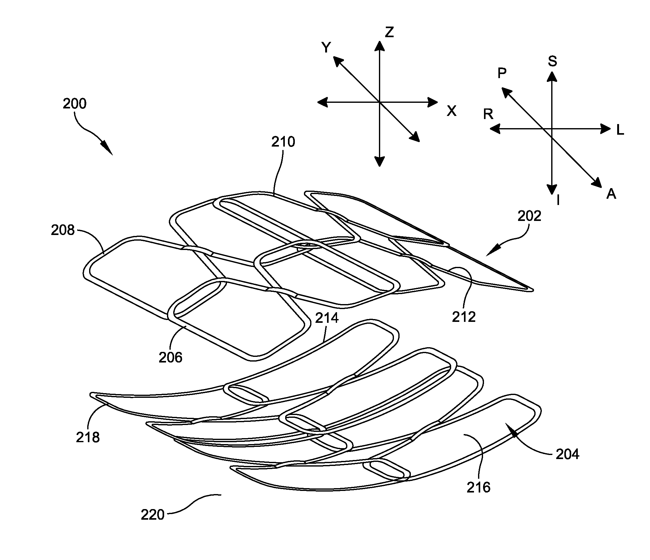
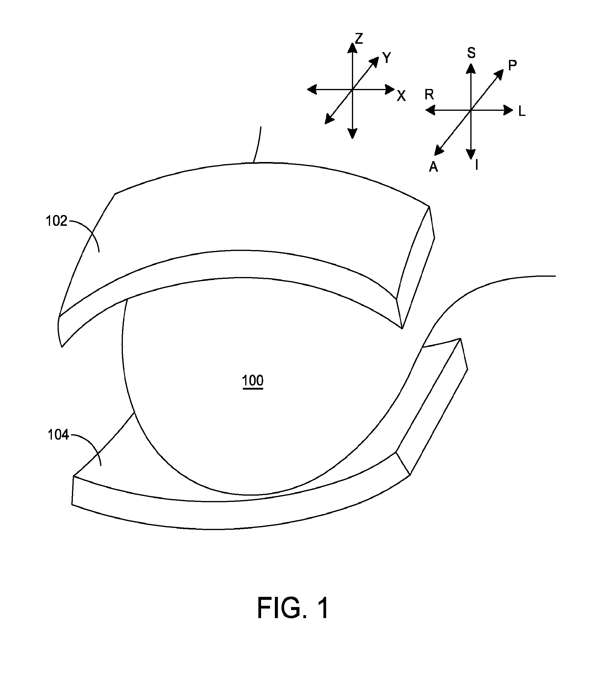
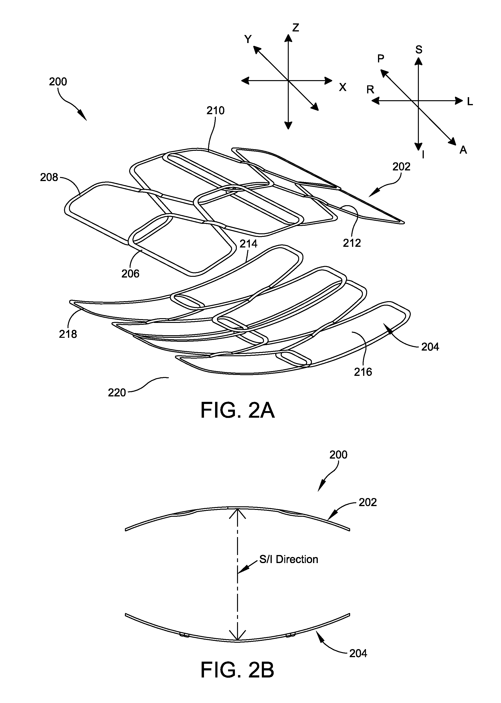
[0030]Aspects and embodiments of this disclosure are directed to system of coils used in the cranio-caudal (or superior / inferior) compression of the breast. Unlike previously disclosed systems, which disclose compression in the left and right lateral directions, cranio-caudal compression of the breast (in the superior / inferior directions) allows the imaging system to image the breast to obtain axial slices without reconfiguring the acquired data for the axial perspectives. If other perspectives are required, they may be reconfigured from the axial data. Aspects and embodiments are directed to coil configurations including a combination overlapping coils disposed in the X-Y plane and having reception sensitivity to a B1 field which is substantially oriented in a direction that is orthogonal to direction of the main B0 magnetic field from the MRI. The combination overlapping coils, according to the embodiments described, allows for acceleration of data acquisition decreasing the time ...


PUM


Abstract

A RF coil compression system for use with an MRI system configured to image a patient's breast is disclosed. In one embodiment, the compression system comprises a first compression plate comprising a first plurality of RF coil elements, which is positioned in a plane oriented orthogonal to a direction of the main magnetic field and the first RF coil elements having a reception sensitivity to a B1 field and is orthogonal to a main magnetic field of the MRI system. The compresses system may further comprise a second compression plate, configured to be positioned opposing the first compression plate and orthogonal to the superior-inferior direction, the second compression plate comprising a second plurality of RF coil elements, the second RF coil elements having a reception sensitivity to a B1 field oriented in a direction substantially orthogonal to the first direction and to the main magnetic field of the MRI system.

Description

RELATED APPLICATIONS[0001]This application claims the benefit under 35 U.S.C. §119 of U.S. Provisional Application No. 61 / 784,787 filed Mar. 14, 2013, the contents of which are hereby incorporate by reference in their entirety.BACKGROUND[0002]1. Field of the Invention[0003]The present invention relates to magnetic resonance imaging (MRI), in particular to a coil system for imaging of breast tissue.[0004]2. Background of the Art[0005]Breast cancer is one of the leading causes of death in women. As a result, early detection is important, and screening of all women is encouraged. Magnetic resonance imaging (MRI) is commonly used to provide non-invasive methods to visualize any abnormalities in the patient's breast tissue.[0006]MRI detects the nuclear magnetic resonance signals given off by protons in the presence of a strong magnetic field after excitation by a radio frequency signal. The nuclear magnetic resonance signals are detected using one or more antenna(e), RF coils or “coils.”...

Claims


Application Information

Patent Timeline
Patent Type & Authority Applications(United States)
IPC IPC(8): A61B5/055A61B5/00
CPCA61B5/004A61B5/4312A61B5/0555G01R33/34084G01R33/3415G01R33/365A61B5/055A61B5/708G01R33/34069
Inventor BRADSHAW, KENNETH
Owner INVIVO CORP
Learn More