
Binary refrigerating apparatus

a technology of refrigerating apparatus and binaries, which is applied in the direction of refrigerating machines, lighting and heating apparatus, compression machines with cascade operation, etc., can solve the problems of oil deterioration and sludge, and achieve the effect of solving combustibility concerns, reducing gwp value, and reducing gwp valu

Inactive Publication Date: 2016-01-21
PANASONIC HEALTHCARE HLDG CO LTD
View PDF5 Cites 33 Cited by
  • Summary
  • Abstract
  • Description
  • Claims
  • Application Information

AI Technical Summary

Benefits of technology

The present invention relates to a binary refrigerating apparatus that uses a refrigerant composition containing difluoroethylene and hexafluoroethane to achieve a refrigerating capacity of -80°C or lower. The use of a refrigerant composition containing difluoroethylene and hexafluoroethane has a small global warming potential (GWP) and low boiling point, which ensures that the refrigerant does not decrease in its cooling capacity, oil deterioration and sludge do not occur, and there is no risk of explosion. Additionally, the use of a refrigerant composition containing difluoroethylene and carbon dioxide further reduces the risk of combustion. The carbon dioxide added to the refrigerant composition helps to inhibit the outlet pressure and temperature from increasing. Overall, the invention provides a more eco-friendly and safe refrigerating apparatus.

Problems solved by technology

However, the above-described R508A has a high GWP of 13200, which has been a problem.
Carbon dioxide (R744) has a small GWP of 1, but has a problem that oil deterioration and sludge occur due to increase in pressure and outlet temperature.

Method used


Image

  • Binary refrigerating apparatus
  • Binary refrigerating apparatus

Examples


example 1

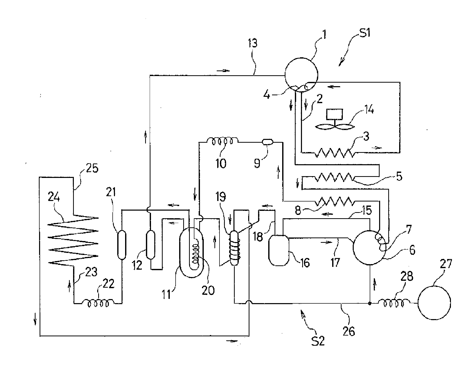
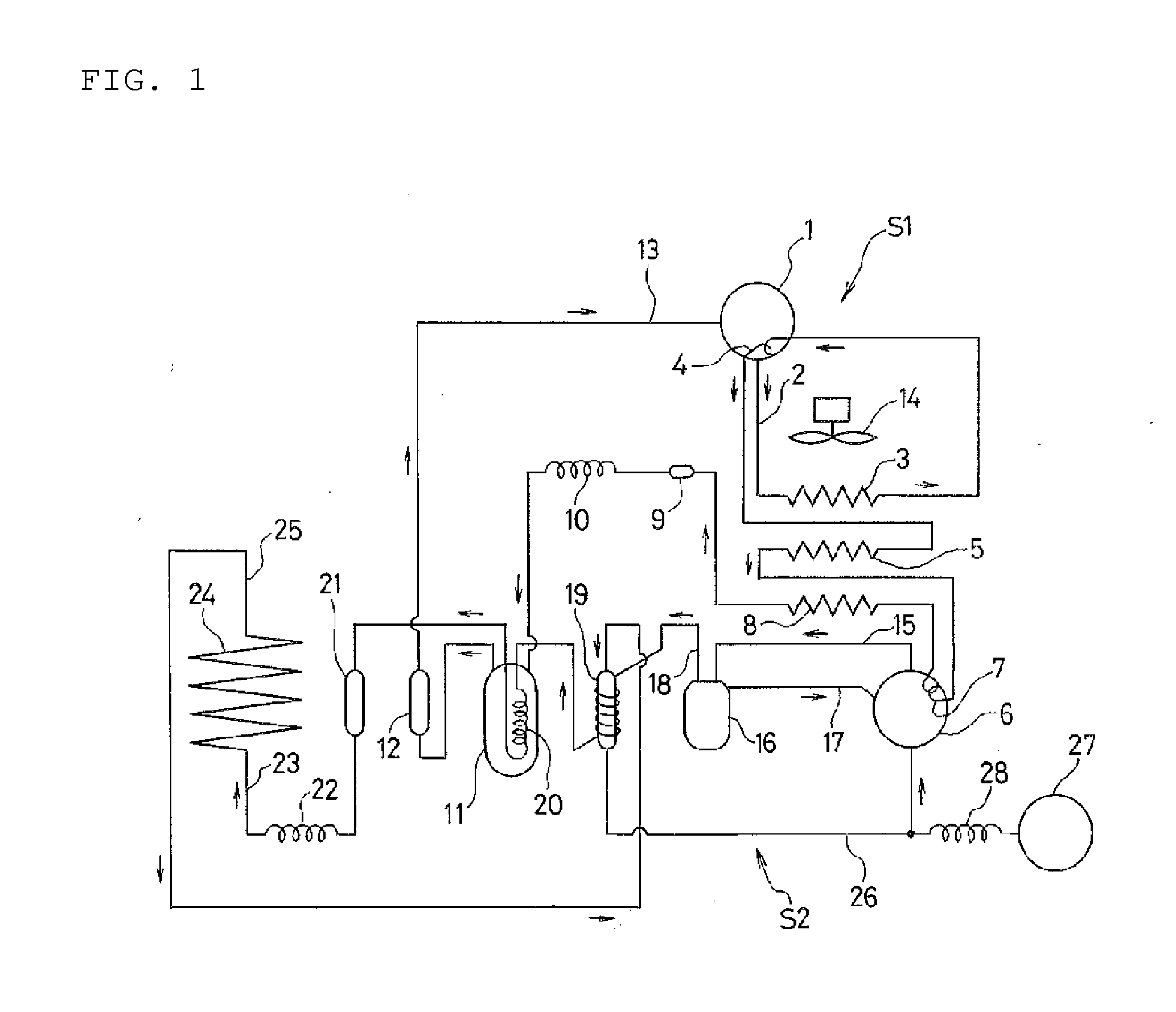
[0056]A binary refrigerating apparatus illustrated in FIG. 1 was stably and continuously operated at an outside air temperature of −10° C. for a long time. Thereafter, a cycle S1 and a cycle S2 were measured for temperatures at the points described below.

[0057]In the high-temperature-side refrigerant cycle S1, a refrigerant composition (GWP value: 1500 or less, boiling point: about −40° C. at atmospheric pressure) containing a non-azeotropic mixture comprising the refrigerant group of difluoromethane (R32), pentafluoroethane (R125), 1,1,1,2-tetrafluoroethane (R134a) and 1,1,3-trifluoroethane (R143a), and 1,1,1,2,3-pentafluoropentene (HFO-1234ze), was filled.

[0058]This refrigerant mixture condensed in each of condensers 3,5 and 8, was decompressed in a capillary tube 10, and flowed into a cascade condenser 11 to evaporate. The temperature at an exit of the cascade condenser 11 was −54.9° C.

[0059]On the other hand, in the low-temperature-side refrigerant cycle S2, a refrigerant compos...

example 2

[0061]In the high-temperature-side refrigerant cycle S1 and the low-temperature-side refrigerant cycle S2, the same refrigerant compositions as those in Example 1 were filled. Then, the binary refrigerating apparatus illustrated in FIG. 1 was stably and continuously operated at an outside air temperature of 31.1° C. for a long time. Thereafter, the cycle S1 and the cycle S2 were measured for temperatures at the points described below.

[0062]The temperature at an exit of the cascade condenser 11 was −35.9° C.

[0063]The temperature of the outlet-side pipe 15 at the refrigerant exit of the compressor 6 in the low-temperature-side refrigerant cycle S2 was 79.0° C.; the temperature of the inlet-side pipe 26 at the refrigerant inlet to the compressor 6 was 7.6° C.; the temperature of the entrance pipe 23 to the evaporator 24 was −90.2° C.; the temperature of the exit pipe 25 from the evaporator 24 was −81.8° C.; and the temperature inside the freezer (not shown) was −87.6° C.

[0064]Also, a r...

example 3

[0065]The binary refrigerating apparatus illustrated in FIG. 1 was stably and continuously operated at an outside air temperature of −0.4° C. for a long time. Thereafter, the cycle S1 and the cycle S2 were measured for temperatures at the points described above.

[0066]In the high-temperature-side refrigerant cycle S1, a refrigerant composition (GWP value: 1500 or less, boiling point: about −40° C. at atmospheric pressure) containing a non-azeotropic mixture comprising the refrigerant group of difluoromethane (R32), pentafluoroethane (R125), 1,1,1,2-tetrafluoroethane (R134a) and 1,1,3-trifluoroethane (R143a), and 1,1,1,2,3-pentafluoropentene (HFO-1234ze), was filled.

[0067]This refrigerant mixture condensed in each of the condensers 3,5 and 8, was decompressed in the capillary tube 10, and flowed into the cascade condenser 11 to evaporate. The temperature at the exit of the cascade condenser 11 was −53.1° C.

[0068]On the other hand, in the low-temperature-side refrigerant cycle S2, a re...


PUM

PropertyMeasurementUnit
temperatureaaaaaaaaaa
boiling pointaaaaaaaaaa

Abstract

A binary refrigerating apparatus employs a refrigerant composition that has a small global-warming potential (GWP) to be earth friendly, can be used as a refrigerant capable of achieving a low temperature of −80° C., and is excellent in refrigerating capacity and other performance. A refrigerant composition used as a low-temperature-side refrigerant is a refrigerant mixture including a non-azeotropic mixture in which 20% by mass or less of carbon dioxide (R744) is mixed to difluoroethylene (R1132a). A refrigerant composition used as a high-temperature-side refrigerant is a combination of: a non-azeotropic mixture comprising the refrigerant group of difluoromethane (R32), pentafluoroethane (R125), 1,1,1,2-tetrafluoroethane (R134a) and 1,1,3-trifluoro ethane (R143a); and 1,1,1,2,3-pentafluoropentene (HFO-1234ze), having a global-warming potential (GWP) of 1500 or less.

Description

TECHNICAL FIELD[0001]The present invention relates to a binary refrigerating apparatus including a refrigerant mixture. The present invention more particularly relates to: a refrigerant composition that has a small global-warming potential (hereinafter, referred to as a GWP) to be earth friendly, can be used as a refrigerant capable of achieving a low temperature of −80° C., and is excellent in refrigerating capacity and other performance; and a binary refrigerating apparatus that includes the refrigerant composition and can actually achieve low temperature.BACKGROUND ART[0002]Conventionally used refrigerants for refrigerators include a non-azeotropic mixture (R407D) of difluoromethane (R32) / pentafluoroethane (R125) / 1,1,1,2-tetrafluoroethane (R134a) (15 / 15 / 70% by mass) and a non-azeotropic mixture (R404A) of pentafluoroethane (R125) / 1,1,1-trifluoroethane (R143a) / 1,1,1,2-tetrafluoroethane (R134a) (44 / 52 / 4% by mass). The boiling point of R407D is about −39° C., and the boiling point o...

Claims


Application Information

Patent Timeline
Patent Type & Authority Applications(United States)
IPC IPC(8): F25B7/00C09K5/04
CPCF25B7/00C09K2205/34C09K2205/22C09K5/045C09K2205/106C09K2205/126F25B9/006
Inventor YUZAWA, JIROTOYOOKA, TAKASHI
Owner PANASONIC HEALTHCARE HLDG CO LTD
Learn More