
Rapid Reset Fire Control

a fire control and rapid technology, applied in the field of firearms, can solve the problems of significantly increasing the maximum potential rate of fire, reducing the time required for the user to prepare the firearm for subsequent firing, etc., and achieves the effect of faster, more controllable and convenient rapid firing of the firearm

Inactive Publication Date: 2016-01-14
BONNER JAMES DILLON
View PDF5 Cites 14 Cited by
  • Summary
  • Abstract
  • Description
  • Claims
  • Application Information

AI Technical Summary

Benefits of technology

The present invention is a fire control group for firearms that has several advantages over existing fire control groups. It allows for faster and more controllable rapid firing of the firearm, requires less force to prepare the firearm for subsequent firings, reduces the time required for the user to prepare the firearm for subsequent firings, and enables easier, faster, and more controllable rapid firing of the firearm when compared to fire control groups with semi-automatic firing modes. It also eliminates the need for the user to repeatedly alternation between contraction and relaxation of the muscles in the user's finger for multiple firings, reduces the burden on the firearm user, and allows for a lighter trigger pull. Additionally, it allows for a firearm with both a low rate of fire and a high rate of fire without requiring additional parts and complexity when compared to firearms which incorporate only a semi-automatic firing mode. It also provides a rate of fire that is lower than the cyclic rate of the fully-automatic firearms, reduces the problems of excessive recoil and excessive ammunition consumption which are commonly associated with the fully-automatic firing mode. It also allows for a firearm which is capable of a high rate of fire which is greater than the rate of fire of typical semi-automatic firing modes, but less than the rate of fire of typical fully-automatic firing modes, without requiring the additional parts and complexity of a rate-reducer as known to the art.

Problems solved by technology

a) The present invention allows for firing multiple live ammunition cartridges without requiring the user to both increase and also decrease the force applied to the trigger with the users finger. This decreases the time required for the user to prepare the firearm for subsequent firings as well as significantly increases the maximum potential rate of fire.

Method used


Image

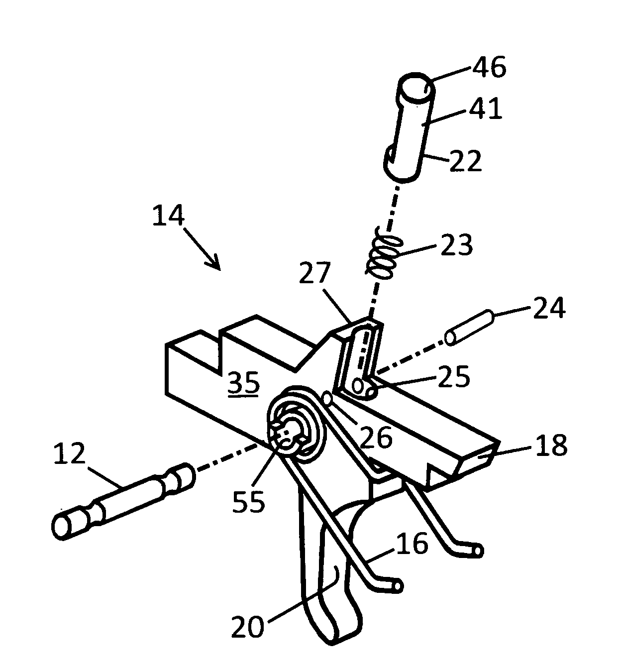
  • Rapid Reset Fire Control
  • Rapid Reset Fire Control
  • Rapid Reset Fire Control

Examples


Embodiment Construction

[0246]The present invention may be embodied in other specific forms without departing from its structures, methods, or other essential characteristics as broadly described herein and claimed hereinafter. The described embodiments are to be considered in all respects only as illustrative, and not restrictive. The scope of the present invention is, therefore, indicated by the appended claims, rather than by the foregoing description. All changes that come within the meaning and range of equivalency of the claims are to be embraced within their scope. The present invention may be embodied in other specific forms without departing from its spirit or essential characteristics. All of the parts discussed herein may be made of metal, plastic or composites. In addition, the parts may be machined, cast, molded, extruded, stamped or forged. The described embodiments are to be considered in all respects only as illustrative and not restrictive. All changes and alternatives that would be known ...


PUM


Abstract

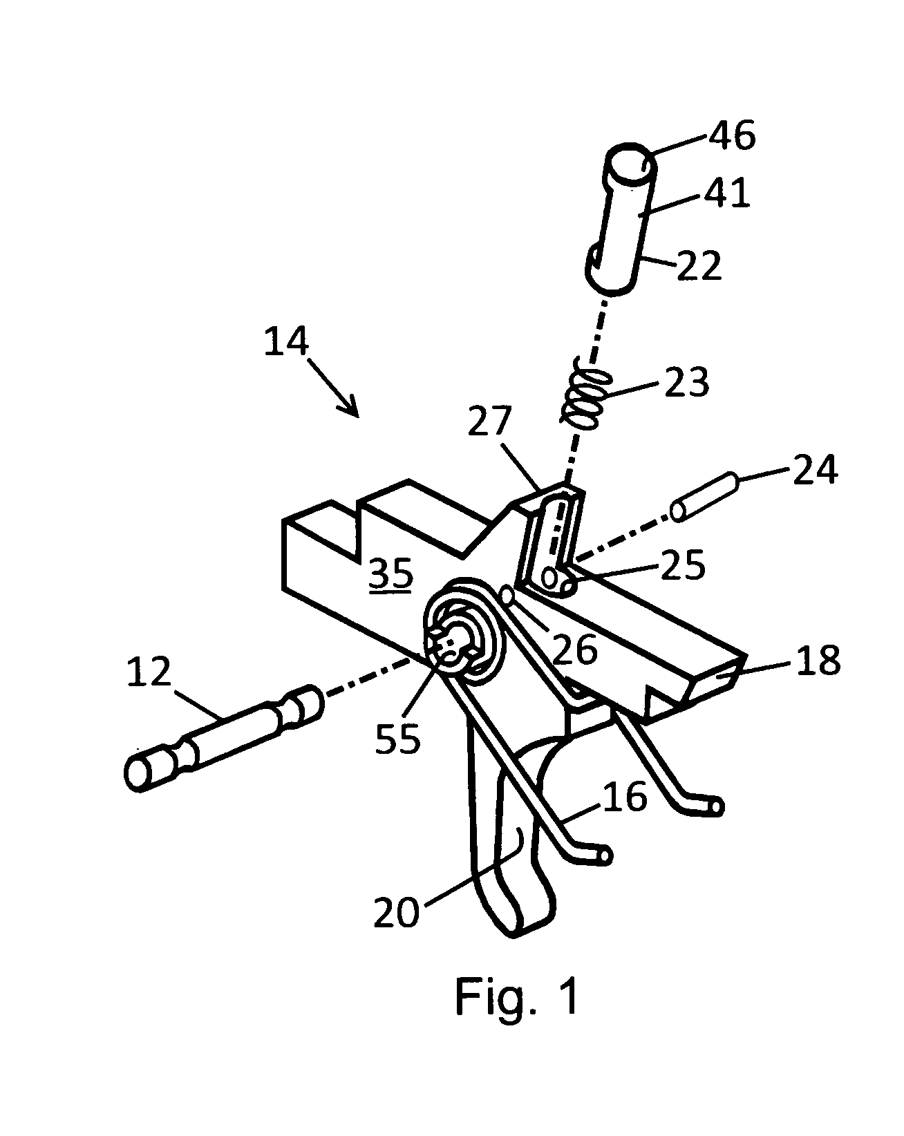
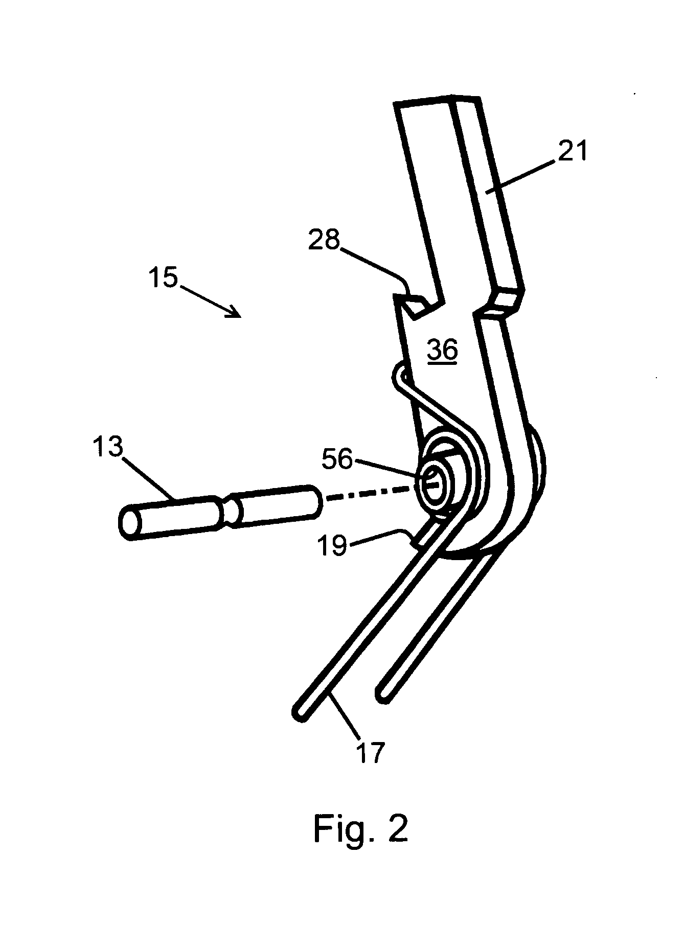
The present invention is an instrument for the rapid firing of a self-loading firearm in a manner which was not previously possible. Some exemplary embodiments of the present invention comprise a fire control group for firearms essentially conforming to semi-automatic fire control groups as known to the art with the addition of novel features, as described herein, which temporarily transfer hammer spring force to the trigger after the firearm has fired live ammunition, resulting in the urging of the trigger to its reset position by hammer spring force. This temporary use of hammer spring force to urge the trigger to its reset position enables more controllable rapid firing of the firearm and other attributes.

Description

CROSS-REFERENCE TO RELATED APPLICATIONS[0001]The present application claims priority of U.S. Provisional Application No. 61 / 965,045 filed Jan. 18, 2014 by the present inventor, titled: Rapid Reset Fire Control.FEDERALLY SPONSORED RESEARCH[0002]NoneSEQUENCE LISTING[0003]NoneFIELD OF THE INVENTION[0004]The present invention relates to firearms. More specifically, the present invention relates to firearm fire control groups comprising a pivotal hammer.BACKGROUND OF THE INVENTION[0005]Self-loading firearms are presently in use throughout the world and have become the dominate firearm type in modern manufacture. Chief among the advantages which have lead to the domination of self-loading firearms is the utility of various rapid fire capabilities which self-loading firearms known to the art are capable of.[0006]Self-loading firearms are those wherein the next live ammunition cartridge loads after a live ammunition cartridge has been fired. Once the firearm is made ready to fire, the user ...

Claims


Application Information

Patent Timeline
IPC IPC(8): F41A19/10F41A19/14
CPCF41A19/14F41A19/10
Inventor BONNER, JAMES, DILLON
Owner BONNER JAMES DILLON
Learn More