
Determining the performance of an environmental system using a predictive model

a technology of environmental system and predictive model, applied in the direction of electric/magnetic computing, analogue processes for specific applications, instruments, etc., can solve the problems of service life remaining, energy and cost savings being skeptical, and replacing existing equipment, so as to achieve cost savings and improve efficiency.

Inactive Publication Date: 2016-01-07
TRANE INT INC
View PDF0 Cites 13 Cited by
  • Summary
  • Abstract
  • Description
  • Claims
  • Application Information

AI Technical Summary

Benefits of technology

The patent describes a system that collects energy usage data from various devices in an environmental system and compares it to determine if there was an efficiency improvement. The system uses a weighting factor to determine the improvement and also predicts the cost savings based on the efficiency improvement. The technical effect of this patent is to provide a tool to measure and improve energy efficiency in real-time, leading to cost savings.

Problems solved by technology

Such incentive programs can have drawbacks, because consumers may be unwilling to replace existing equipment which, while not providing state-of-the-art energy efficiency, may otherwise be fully functional and have considerable service life remaining.
In other instances, consumers may be skeptical about actually realizing the energy and cost savings promised as a result of purchasing the new equipment and consequently, are reluctant to make a purchase.

Method used


Image

  • Determining the performance of an environmental system using a predictive model
  • Determining the performance of an environmental system using a predictive model
  • Determining the performance of an environmental system using a predictive model

Examples


Embodiment Construction

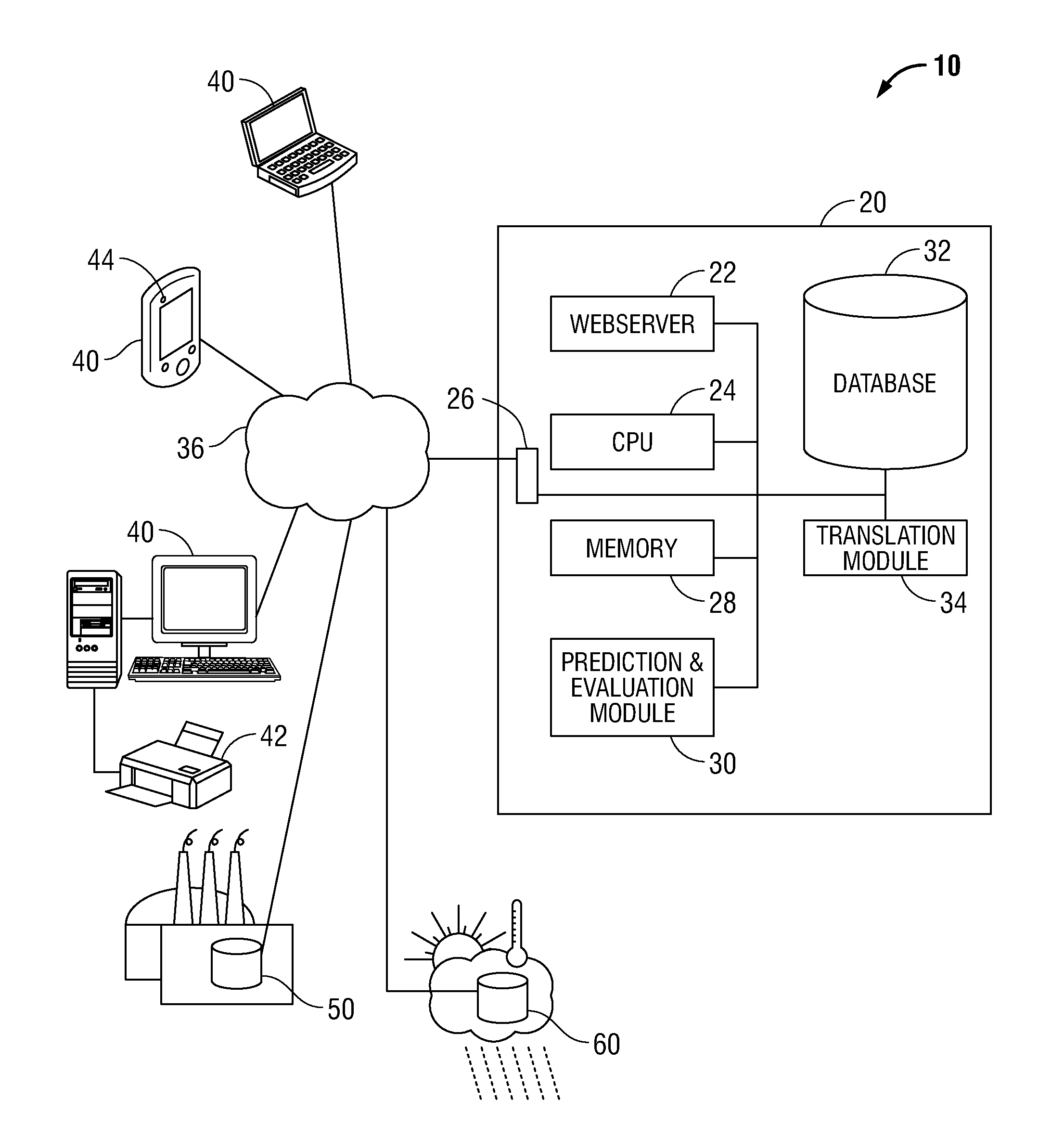
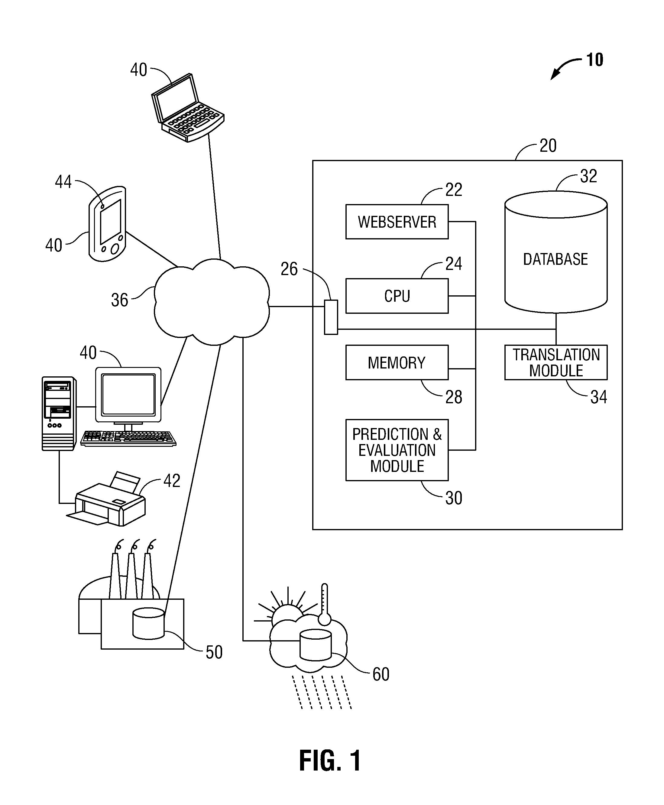
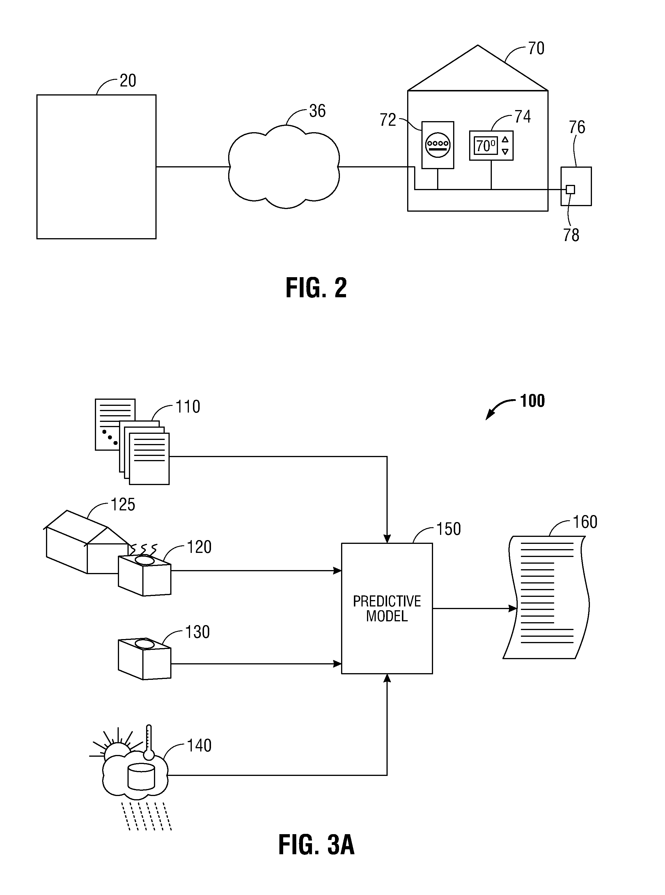
[0024]Particular illustrative embodiments of the present disclosure are described hereinbelow with reference to the accompanying drawings; however, the disclosed embodiments are merely examples of the disclosure, which may be embodied in various forms. Well-known functions or constructions and repetitive matter are not described in detail to avoid obscuring the present disclosure in unnecessary or redundant detail. Therefore, specific structural and functional details disclosed herein are not to be interpreted as limiting, but merely as a basis for the claims and as a representative basis for teaching one skilled in the art to variously employ the present disclosure in virtually any appropriately detailed structure. In this description, as well as in the drawings, like-referenced numbers represent elements which may perform the same, similar, or equivalent functions. The word “exemplary” is used herein to mean “serving as an example, instance, or illustration.” Any embodiment descri...


PUM


Abstract

Disclosed herein are systems and methods for predicting an energy savings resulting from the replacement of existing equipment with new equipment. In the example embodiments, the energy saving prediction is utilized to create a customized warranty for an individual customer of an HVAC system or subcomponent thereof. Historical energy usage, historical climate data, old and new equipment parameters, and customer use data is input to a predictive modeling algorithm, which determines an energy savings prediction. Alternative models may be employed and a weighting factor applied to each to arrive at an improved energy savings prediction. The energy savings prediction is utilized to warranty to the customer an estimated dollar savings that will result from the installation of the new equipment. The warranty provides that, in the event the predicted energy savings is not realized, the customer is entitled to receive a dollar amount representing the shortfall in warranted energy savings.

Description

CROSS-REFERENCE TO RELATED APPLICATION[0001]This application claims the benefit of and priority to U.S. Provisional Application Ser. No. 62 / 021,535 entitled “DETERMINING THE PERFORMANCE OF AN ENVIRONMENTAL SYSTEM USING A PREDICTIVE MODEL” filed Jul. 7, 2014, the entirety of which is hereby incorporated by reference herein for all purposes.BACKGROUND[0002]1. Technical Field[0003]The present disclosure is directed to systems and methods for determining the performance of an energy-consuming system using a predictive model, and more particularly, to the creation of customer-specific warranty terms based at least in part upon the application of a predictive model to customer usage data, historical environmental data, and equipment data.[0004]2. Background of Related Art[0005]Increased energy efficiency and reduced energy costs are common goals shared by many throughout the world. These goals may be achieved by modifying use patterns, such as by car-pooling to work, or by lowering a ther...

Claims


Application Information

Patent Timeline
IPC IPC(8): G06F17/50G06Q10/06G06Q30/02G06Q50/06
CPCG06F17/5009G06Q30/0234G06Q50/06G06Q10/067G06Q30/0215G06F30/20
Inventor CRAWFORD, ROY R.KRAFT, WAYNE N.GROSKREUTZ, MARK E.ROLLES, FRANKLIN K.
Owner TRANE INT INC
Learn More