Imaging lens

Active Publication Date: 2016-01-07
TOKYO VISIONARY OPTICS CO LTD
View PDF4 Cites 53 Cited by
  • Summary
  • Abstract
  • Description
  • Claims
  • Application Information

AI Technical Summary

Benefits of technology

The present invention provides an imaging lens that has high resolution with satisfactory correction of aberrations. The lens has a unique structure that includes three lenses with refractive powers arranged in a specific order. The lenses are made of materials that meet certain conditions to restrain chromatic aberration and astigmatism. The lens can also be designed to have a small size and to restrain the incident angle of light beams to the image plane within a specific range. This helps to prevent darkening of the image periphery and improves image-forming performance. The lens is ideal for mounting in small-sized cameras, and is especially suitable for high-resolution photography.

Problems solved by technology

However, the increase of the number of lenses easily causes an increase in the size of the imaging lens.
Therefore, the lens configuration having a large number of lenses is disadvantageous for mounting in a small-sized camera such as the above-described smartphones.
In case of a lens configuration composed of six lenses, since the number of lenses that compose an imaging lens is large, it is somewhat disadvantageous for downsizing the imaging lens.
Here, such a problem is not specific to the imaging lens to be mounted in the cellular phones and smartphones.
Rather, it is a common problem even for an imaging lens to be mounted in a relatively small camera such as digital still cameras, portable information terminals, security cameras, vehicle onboard cameras, and network cameras.

Method used


Image

  • Imaging lens
  • Imaging lens
  • Imaging lens

Examples


Embodiment Construction

[0069]Hereunder, referring to the accompanying drawings, an embodiment of the present invention will be fully described.

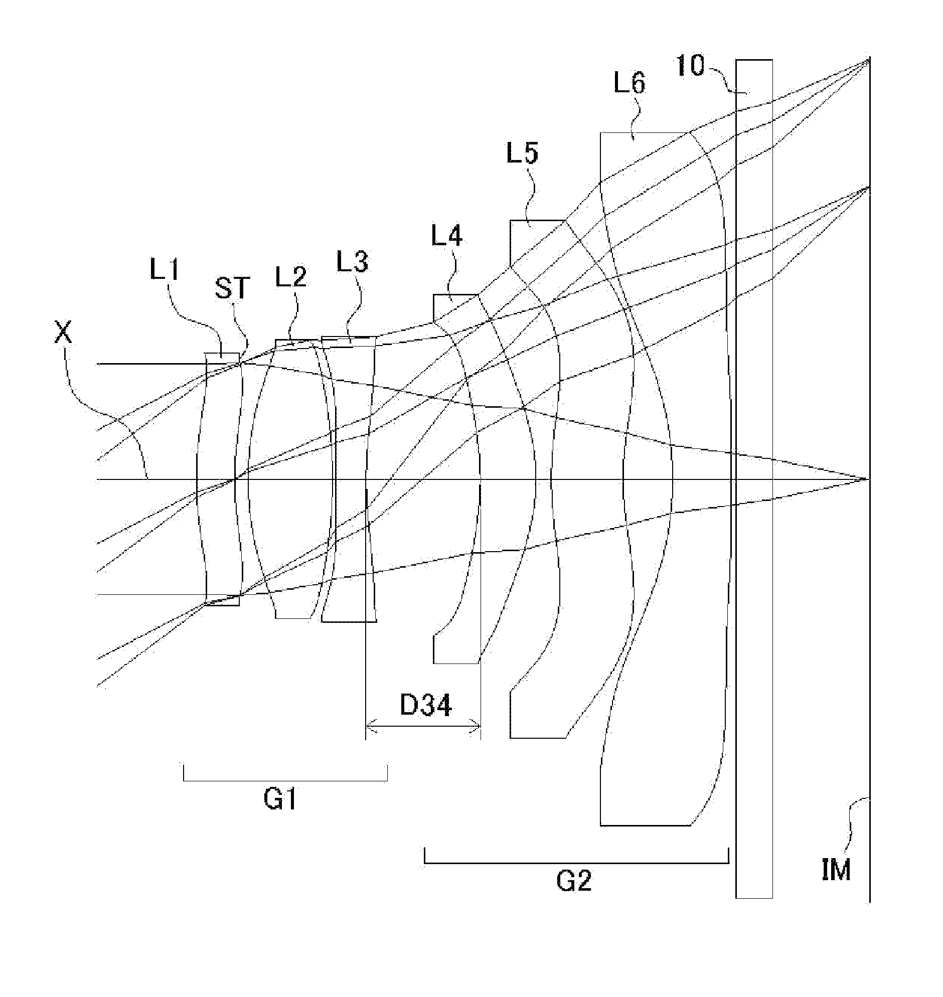
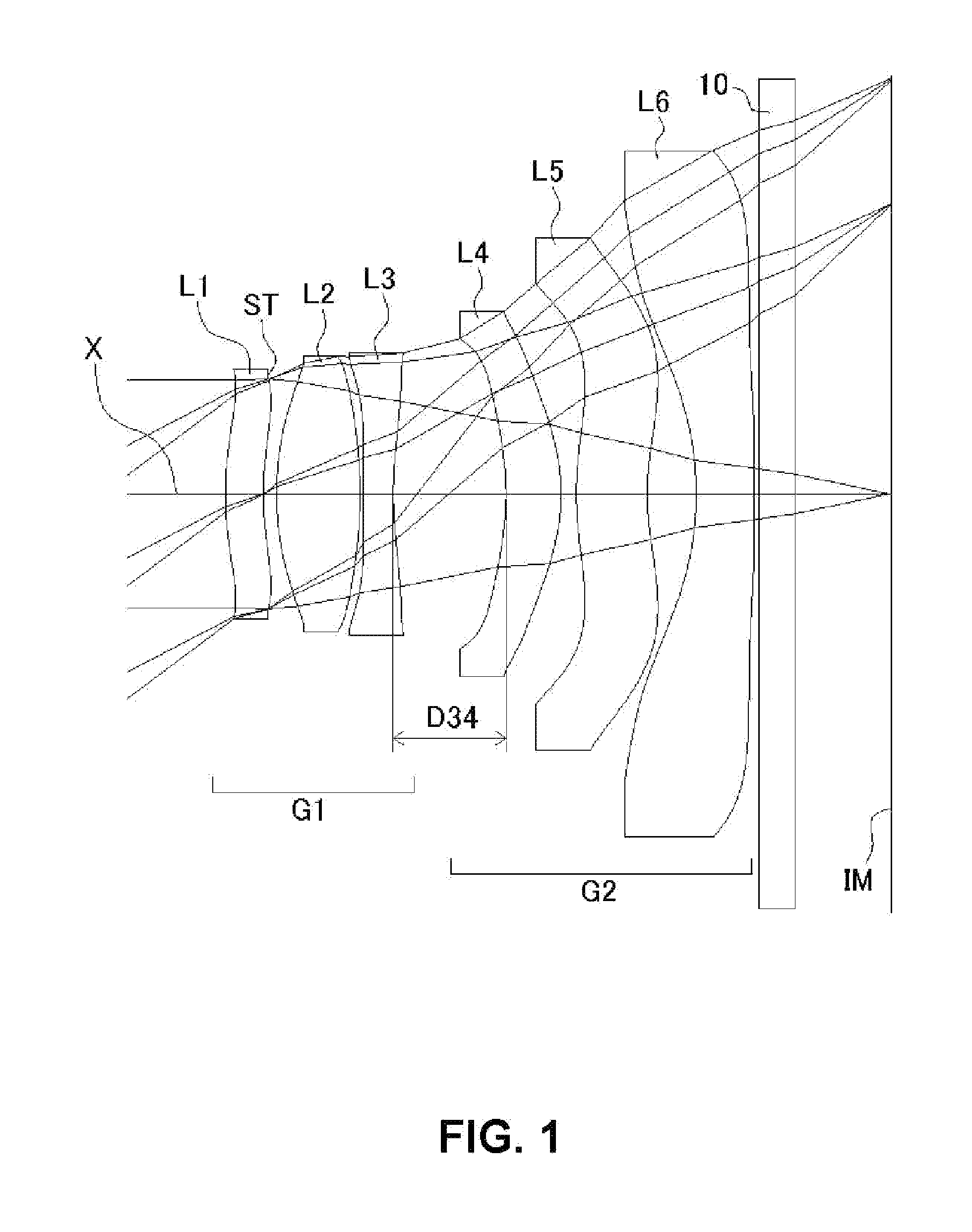
[0070]FIGS. 1, 4, 7, 10, 13, 16, and 19 are schematic sectional views of the imaging lenses in Numerical Data Examples 1 to 7 according to the embodiment, respectively. Since the imaging lenses in those Numerical Data Examples have the same basic configuration, the lens configuration of the embodiment will be described with reference to the illustrative sectional view of Numerical Data Example 1.

[0071]As shown in FIG. 1, according to the embodiment, the imaging lens includes a first lens group G1 having positive refractive power, and a second lens group G2 having negative refractive power, arranged in the order from an object side to an image plane side. Between the second lens group G2 and an image plane IM of an imaging element, there is provided a filter 10. The filter 10 is omissible.

[0072]The first lens group G1 includes a first lens L1 having positive refract...


PUM


Abstract

An imaging lens includes a first lens group having positive refractive power and a second lens group having negative refractive power, arranged in this order from an object side to an image plane side. The first lens group includes a first lens having positive refractive power, a second lens having positive refractive power, and a third lens having negative refractive power. The second lens group includes a fourth lens having positive refractive power, a fifth lens, and a sixth lens having negative refractive power. The first lens has a specific focal length. The first to third lenses have specific Abbe's numbers.

Description

BACKGROUND OF THE INVENTION AND RELATED ART STATEMENT[0001]The present invention relates to an imaging lens for forming an image of an object on an imaging element such as a CCD sensor and a CMOS sensor. In particular, the present invention relates to an imaging lens suitable for mounting in a relatively small camera such as a camera to be built in a portable device including a cellular phone and a portable information terminal, a digital still camera, a security camera, a vehicle onboard camera, and a network camera.[0002]In these years, in place of cellular phones that are intended mainly for making phone calls, so-called “smartphones”, which are multi-functional cellular phones that can be used to execute various application software as well as making phone calls, have been more widely used. By executing application software on a smartphone, the smartphone can be used, for example, as a digital still camera, a car navigation system, or the like. In order to execute the functions,...

Claims


Application Information

Patent Timeline
IPC IPC(8): G02B13/00G02B9/62
CPCG02B9/62G02B13/0045G02B5/005G02B13/001G02B13/002G02B13/18G02B27/0025
Inventor KUBOTA, YOJIKUBOTA, KENICHIHIRANO, HITOSHIFUKAYA, HISAO
Owner TOKYO VISIONARY OPTICS CO LTD
Why Eureka
Try Eureka