
Method for making an impeller from sector segments

a technology of sector segments and impellers, which is applied in the direction of machines/engines, non-electric welding apparatus, waterborne vessels, etc., can solve the problems of many working days, process is very time-consuming, and difficult processing, and achieves shortening the machining time and high quality

Active Publication Date: 2016-01-07
NUOVO PIGNONE TECH SRL
View PDF4 Cites 9 Cited by
  • Summary
  • Abstract
  • Description
  • Claims
  • Application Information

AI Technical Summary

Benefits of technology

The present invention provides a new method for manufacturing impellers that are simpler and faster than previous methods. The method can produce high-quality and reliable impellers. This invention also allows for the use of advanced manufacturing techniques and enables the creation of impellers with complex geometries.

Problems solved by technology

The impeller can be constructed from one single solid piece by full milling, but this process is very difficult and time consuming due to the limited accessibility given the complex shape of the flow passages.
The process is very time consuming and many working days are necessary to produce a single impeller.
With welding filling the internal junction between blades and main body or shroud given the lack of good accessibility is very difficult and welding defects easily occur in the fixing and thus the risk of cracking and deformation, i.e. thermal distortion, due to locally high temperatures, can become very high.
In definitive it is very hard by using state of the art techniques to obtain an impeller with the high quality and reliability required.

Method used


Image

  • Method for making an impeller from sector segments
  • Method for making an impeller from sector segments
  • Method for making an impeller from sector segments

Examples


Embodiment Construction

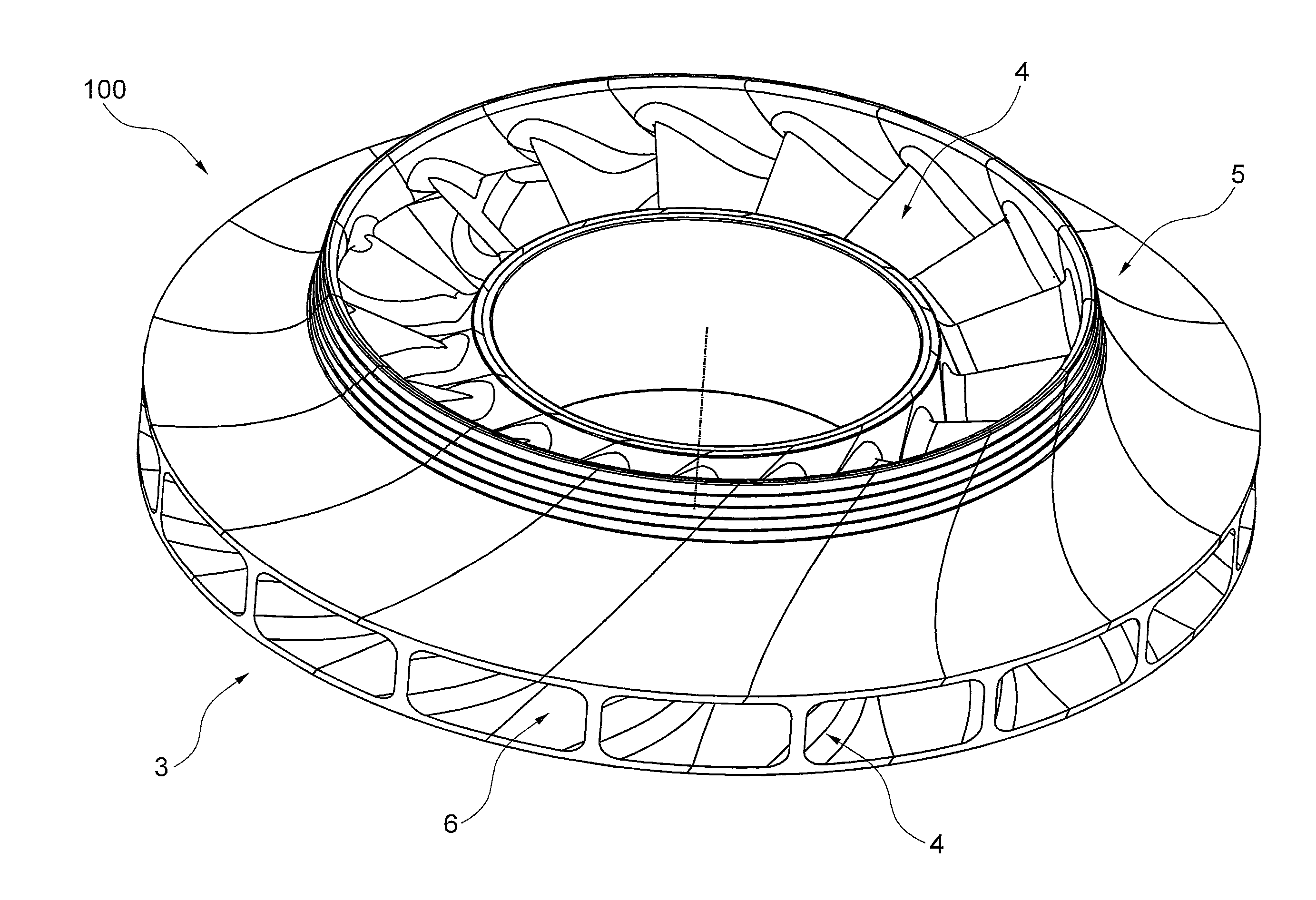
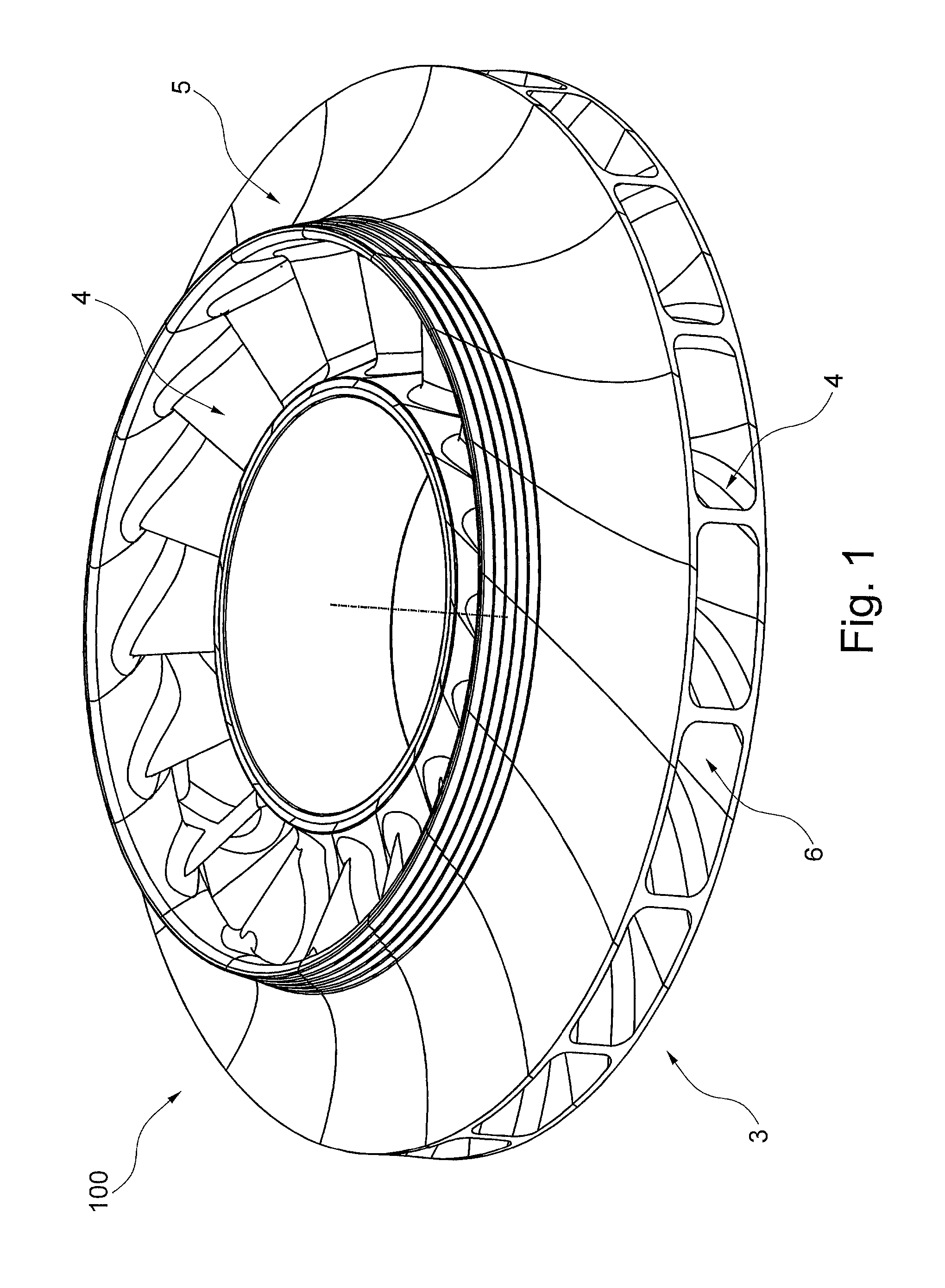
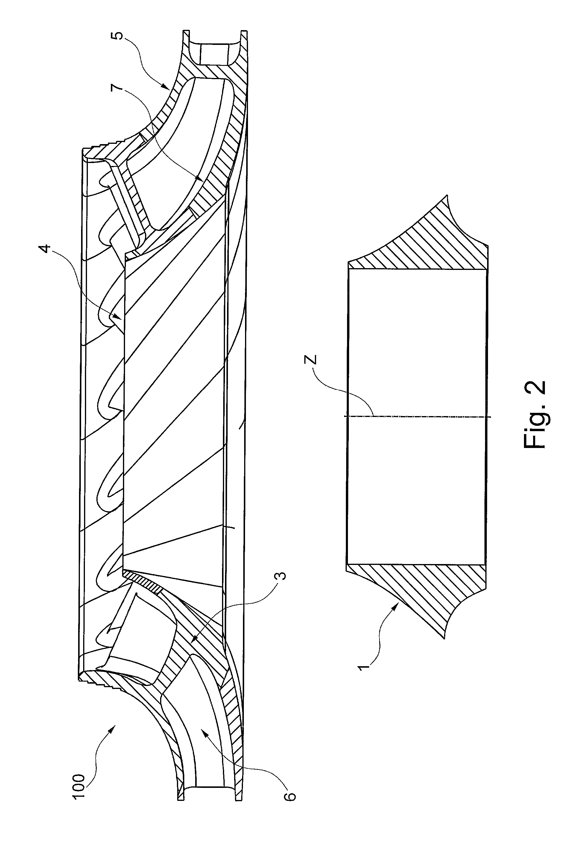
[0017]With reference to FIGS. 1 and 2 there is shown a perspective representation of a 3D impeller generally indicated with reference numeral 100. The impeller 100 is formed by a disk shaped main body 3 having a rear surface and a front surface 7. The front surface 7 starting from an outer circular portion almost flat and perpendicular to the rotating axis Z of the machine gradually curves towards the central region in the direction of the axis Z, the central region being a circular aperture adapted to mate with the external surface of the hub 1 or of the rotor shaft. A shroud 5 roughly following the shape of the front surface 7 of the body 3 is separated from this front surface by the blades 4. Air passages 6 through which the air is compressed are formed by the internal surface of the shroud, the front surface 7 of the body 3 and the lateral surfaces of the blades 4. In this type of impeller for a centrifugal compressor, the air flow enters the passages tangentially to the flat su...


PUM


Abstract

A manufacturing technique for impellers for a centrifugal rotating machine is provided. The impeller is made by composition of single vanes pieces that fit to the hub or directly to the rotor shaft by welding, friction welding or a mechanical locking system. The manufacturability of the segments is easy fast and cheap and make it possible to use advanced manufacturing technologies like additive manufacturing of the type of Direct Metal Laser Melting.

Description

FIELD OF INVENTION[0001]Embodiments of the present invention relate to a method of manufacture of an impeller for a centrifugal compressor.BACKGROUND ART[0002]An impeller for a centrifugal rotating machine, such as a centrifugal compressor, is generally composed of an approximately disk shaped main body having a front and a rear surfaces, with respect to the direction of the fluid flow, provided with a central circular hole that fits with a hub attached to a rotating axis, a shroud having a front and a rear surfaces that is arranged at an interval outward of the main body and a series of blades that couple the front surface of the main body and the rear surface of the shroud. A series of passages are formed by the front surface of the main body, the rear surface of the shroud and the side surfaces of the blades, the passages serving as a flow passage for compressing air. Generally the blades follow a curved line bending in both radial and axial direction. The front surface of the ma...

Claims


Application Information

Patent Timeline
IPC IPC(8): F04D29/28F04D17/10F04D29/62
CPCF04D29/284F04D29/624F04D17/10B23K20/12F01D5/34B23P15/006B23K2101/001
Inventor PALOMBA, SERGIOLORENZI, LORENZOBIANCHI, LORENZO
Owner NUOVO PIGNONE TECH SRL
Learn More