Oil separator
a technology of oil separator and oil tank, which is applied in the direction of separation process, auxillary pretreatment, positive displacement liquid engine, etc., and can solve problems such as operation defects
- Summary
- Abstract
- Description
- Claims
- Application Information
AI Technical Summary
Benefits of technology
Problems solved by technology
Method used
Image
Examples
first embodiment
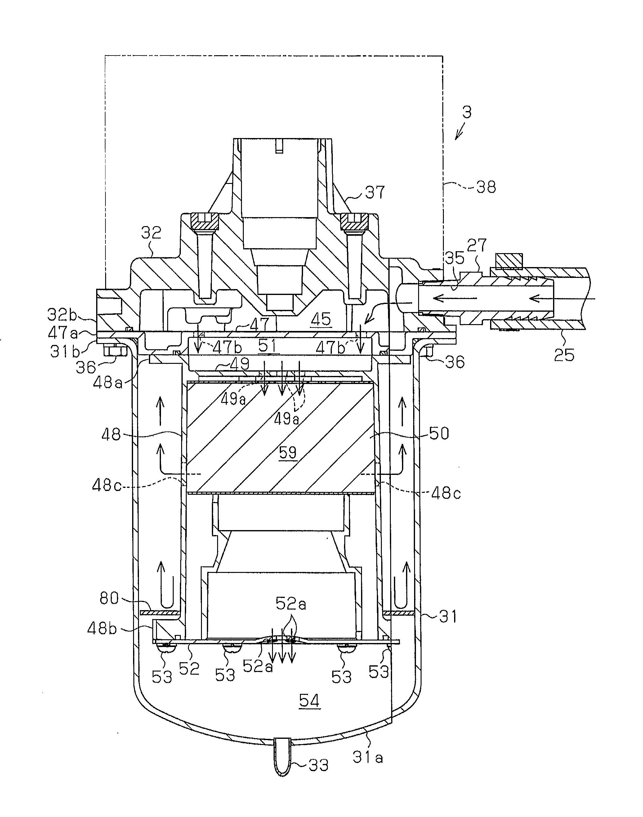
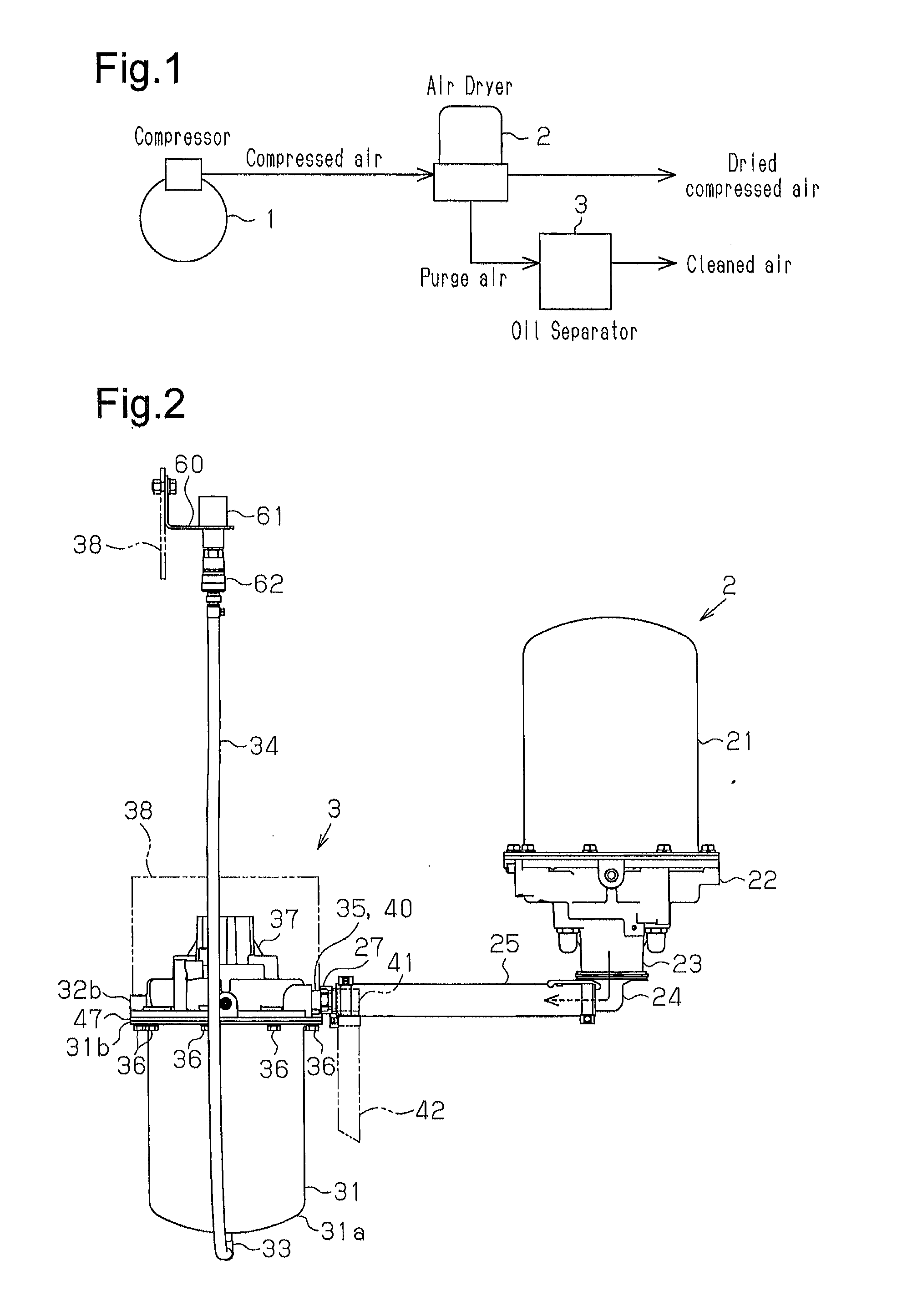
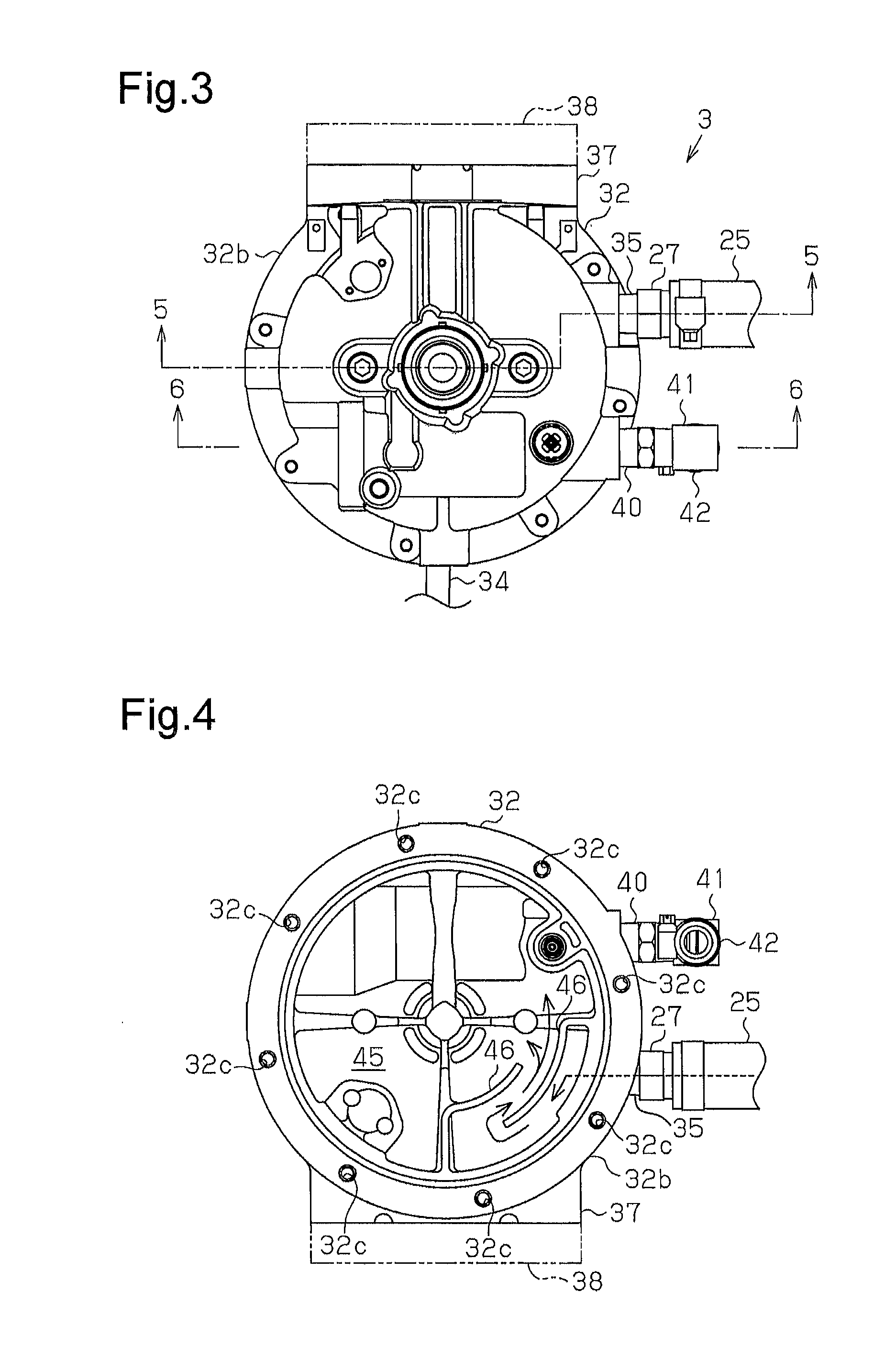
[0034]An oil separator according to a first embodiment will now be described with reference to FIGS. 1 to 8.
[0035]As shown in FIG. 1, vehicles such as trucks, buses, and construction machines utilize compressed air delivered from a compressor 1 to control systems such as brakes and suspensions. Thus, an air dryer 2, which removes oil and water in the compressed air and supplies dried air, is located downstream of the compressor 1 of a pneumatic system. The air dryer 2 incorporates a desiccant. The air dryer 2 performs dehumidification to remove oil and water from the compressed air and regeneration to regenerate the desiccant by removing the oil and water adsorbed by the desiccant and discharging them to the outside.
[0036]In the present embodiment, since air (purge air) that is discharged from the air dryer 2 during regeneration of the desiccant contains oil together with water, an oil separator 3 is provided downstream of the compressor 1 of the pneumatic system, taking the burden ...
second embodiment
[0062]An oil separator according to a second embodiment will now be described with reference to FIG. 11. The present embodiment is different from the first embodiment in that a baffle plate is fixed. Differences from the first embodiment will mainly be discussed below.
[0063]As shown in FIG. 11, a cylindrical baffle plate 90 with a closed end is fixed to the lower end of the accommodation member 48 in the case 31. The baffle plate 90 opens in the direction away from the accommodation member 48. The baffle plate 90 replaces the support lid 52 of the first embodiment. That is, the baffle plate 90 supports the accommodated urethane foam block 50 and is fixed with the screws 53. The outer diameter of the outer circumferential surface 91 of the baffle plate 90 is substantially equal to the inner diameter of the inner circumferential surface 31c of the case 31. The baffle plate 90 has through holes 92, which permit oil and water removed by the urethane foam block 50 to drop. Thus, the inte...
third embodiment
[0070]An oil separator according to a third embodiment will now be described with reference to FIG. 12. The present embodiment is different from the first embodiment in that a baffle plate is fixed and that a replaceable spin-on filter cartridge is used. Differences from the first embodiment will mainly be discussed below.
[0071]As shown in FIG. 12, a cylindrical baffle plate 100 is fixed to the cover 47 with bolts (not shown). A filter cartridge 110 is attached to the baffle plate 100. The filter cartridge 110 accommodates a urethane foam block 50, which is, for example, a sponge. The baffle plate 100 includes a small diameter portion 101, a large diameter portion 102, a step portion 103 between the small diameter portion 101 and the large diameter portion 102, and a flange 104 provided at an edge of the small diameter portion 101. The outer diameter of the small diameter portion 101 is smaller than the inner diameter of the case 31. The outer diameter of the large diameter portion ...
PUM
 Abstract
Description
Claims
Application Information
 - Generate Ideas
- Intellectual Property
- Life Sciences
- Materials
- Tech Scout
- Unparalleled Data Quality
- Higher Quality Content
- 60% Fewer Hallucinations
Browse by: Latest US Patents, China's latest patents, Technical Efficacy Thesaurus, Application Domain, Technology Topic, Popular Technical Reports.
© 2025 PatSnap. All rights reserved.Legal|Privacy policy|Modern Slavery Act Transparency Statement|Sitemap|About US| Contact US: help@patsnap.com


