
Sensor adapter cable

a technology of adapter cable and sensor, which is applied in the direction of diagnostic recording/measuring, application, coupling device connection, etc., can solve the problem that the solution cannot affect the ability of each of the spo2 technologies to operate correctly

Active Publication Date: 2015-12-31
MASIMO CORP
View PDF2 Cites 245 Cited by
  • Summary
  • Abstract
  • Description
  • Claims
  • Application Information

AI Technical Summary

Benefits of technology

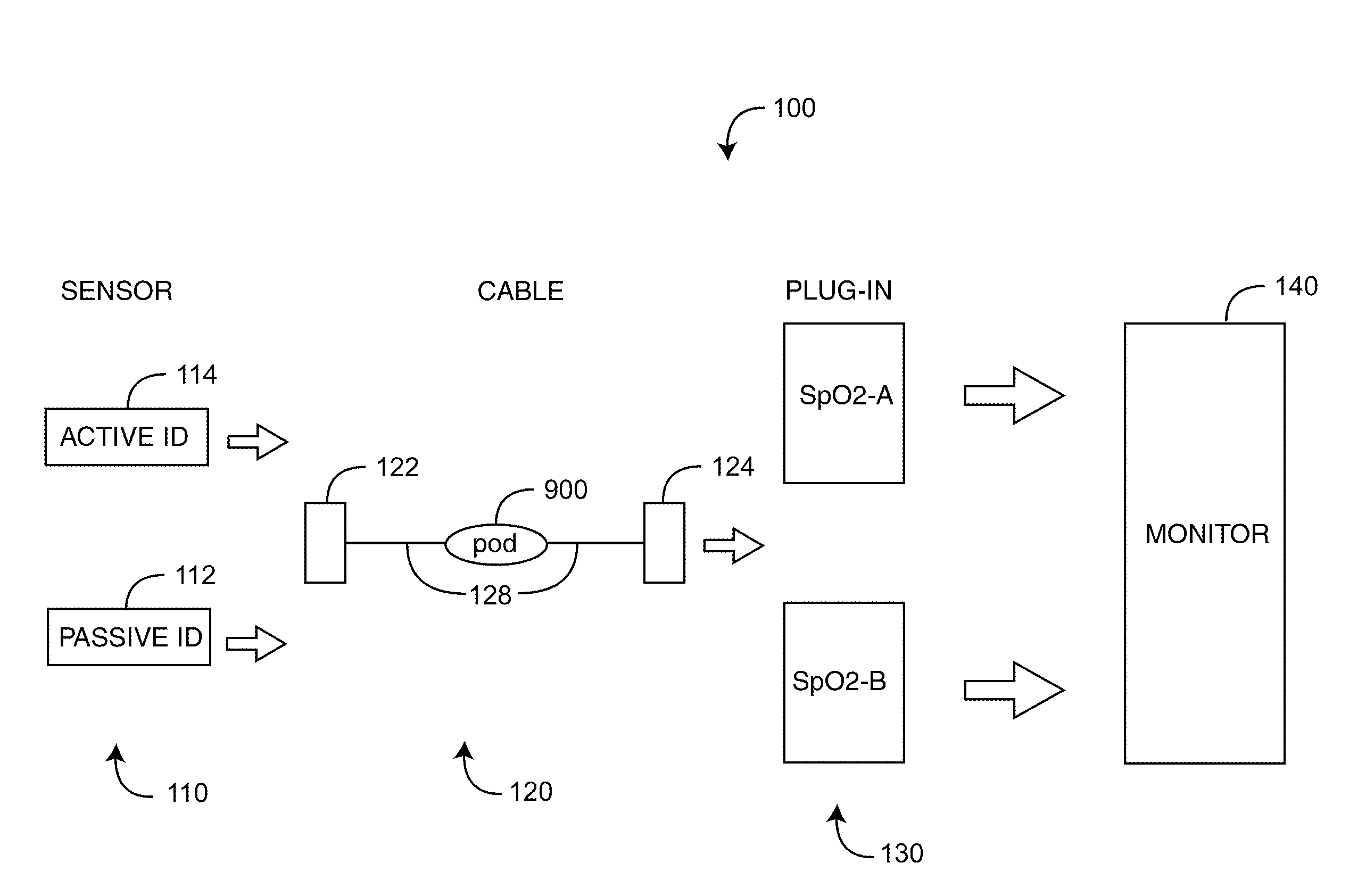
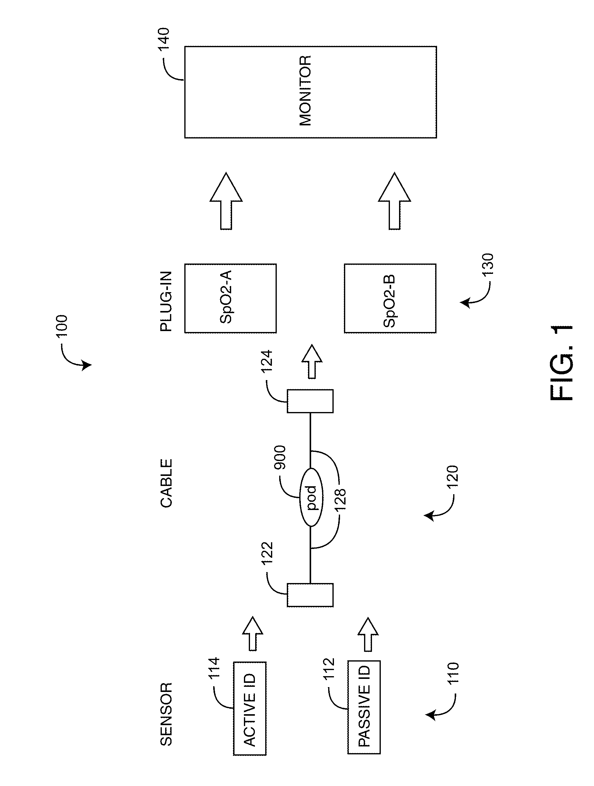
[0007]One aspect of a sensor adapter cable provides medical personnel with the convenience of utilizing otherwise incompatible optical sensors with multiple blood parameter plug-ins to a physiological monitor. The plug-ins each have keyed connectors that mechanically lock-out incompatible sensors in addition to readers that poll sensor identification components in each sensor so as to electrically lock-out incompatible sensors. The sensor adapter cable has a sensor connector, a plug-in connector, an interconnection cable and a pod. The sensor connector mechanically connects to a predetermined sensor and electrically communicates with sensor electrical elements within the predetermined sensor. The plug-in connector mechanically connects to a predetermined plug-in and electrically communicates with lug-in electrical elements within the predetermined plug-in. An interconnection cable mechanically attaches between and provides electrical communications between the sensor connector and the plug-in connector. A pod is incorporated within the interconnecting cable that electrically interfaces the sensor connector to the plug-in connector.

Problems solved by technology

Further, this solution cannot impact the ability of each of the SpO2 technologies to operate correctly across its entire range of sensors and accessories.

Method used


Image

  • Sensor adapter cable
  • Sensor adapter cable
  • Sensor adapter cable

Examples


embodiment 200

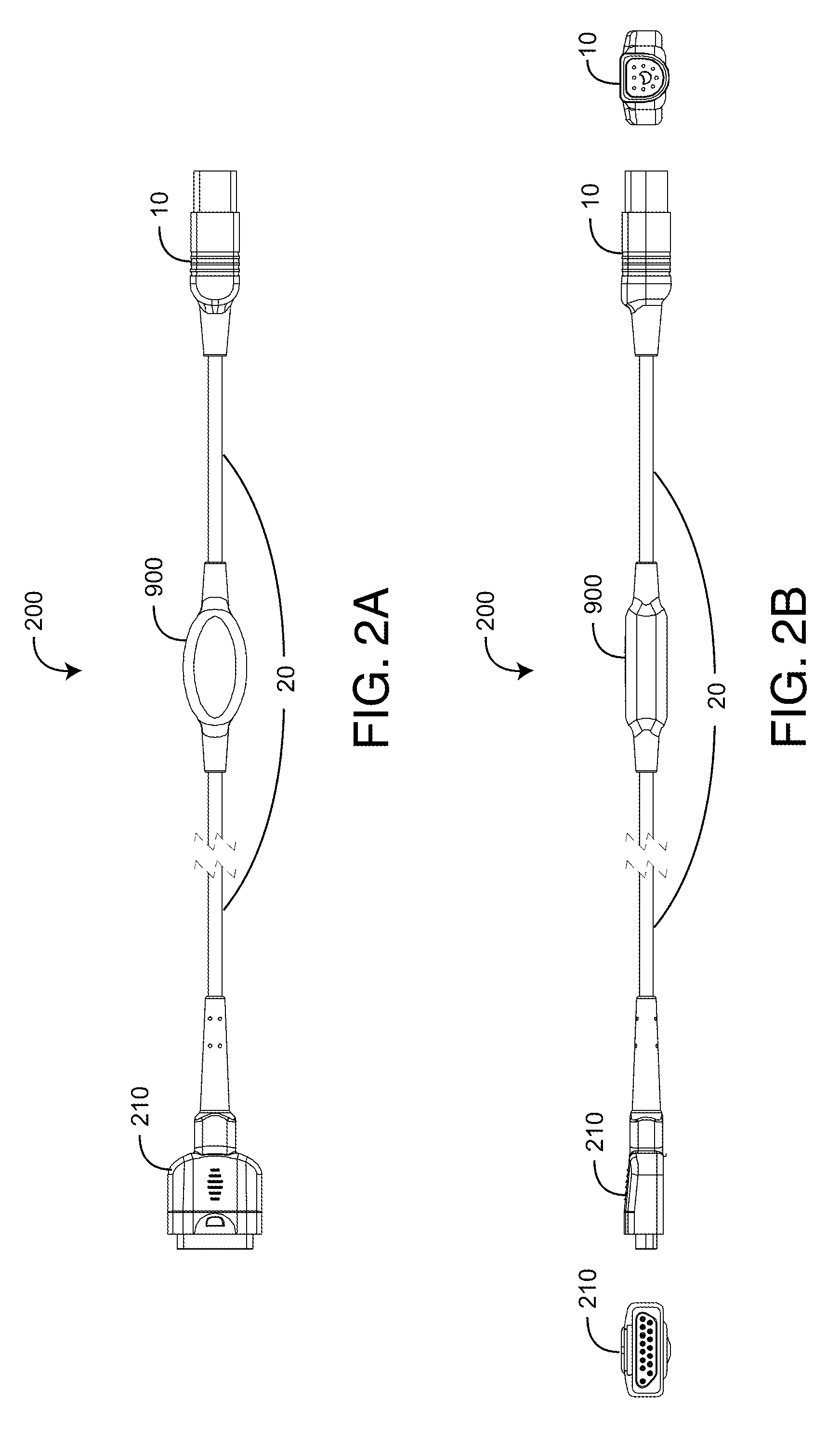
[0027]FIGS. 3A-C further illustrate a sensor adapter cable embodiment 200, showing the respective pinouts of the M15 connector 210 and the D8 connector 10. Also shown are the corresponding cable 20 color-coded wires, inner shield and outer shield. Further shown is a sensor adapter circuit 400 and its connections relative to the connectors 10, 210 and cable 20 wires.

[0028]FIG. 4 illustrates the sensor adapter circuit 400 having plug-in connections 410 and sensor connections 420. The plug-in connections 410 (J1, J2, J3) connect to the plug-in connector 10 (FIGS. 2-3, 5-6, 7-8). The sensor connections 420 (J4, J5) connect to the sensor connector 210 (FIGS. 2-3); 510 (FIG. 5-6) or 710 (FIGS. 7-8). Table 1 below defines the signal names and associated connections to the plug-in connector pins.

TABLE 1Adapter Circuit and Plug-in Connector PinoutsReferencePlug-inSignal NameDesignationConnector Pin #R-TYPE / EEPROMJ23RCAL / CONTROLJ14OUTER SHIELDJ37

[0029]The switch components 430, 440 used in th...

embodiment 500

[0032]FIGS. 6A-C further illustrate a sensor adapter cable embodiment 500, showing the respective pinouts of the MC8 connector 510 and the D8 connector 10. Also shown are the corresponding cable 20 color-coded wires, inner shield and outer shield. Further shown are the sensor adapter circuit 400 connections relative to the connectors 10, 510 and cable 20 wires.

embodiment 700

[0033]FIGS. 7A-B illustrate a sensor adapter cable embodiment 700 employing a DB9 sensor connector 710 and a D8 plug-in connector 10. A cable 20 interconnects the sensor connector 710 and the plug-in connector 10. A pod 900 integrated with the cable 20 contains a sensor adapter circuit 400 (FIG. 4) that insures electrical compatibility between a passive and an active ID 110 (FIG. 1) and a particular plug-in 130 (FIG. 1).

[0034]FIGS. 8A-C further illustrate a sensor adapter cable embodiment 700, showing the respective pinouts of the DB9 connector 710 and the D8 connector 10. Also shown are the corresponding cable 20 color-coded wires, inner shield and outer shield. Further shown are the sensor adapter circuit 400 connections relative to the connectors 10, 710 and cable 20 wires.

[0035]FIGS. 9A-B illustrate a pod 900 that splices the sensor adapter circuit 400 (FIG. 4) into the sensor adapter cable 20. The pod 900 has a overmold 910, a premold 920, a copper foil shield 930, a circuit bo...


PUM


Abstract

A sensor adapter cable provides medical personnel with the convenience of utilizing otherwise incompatible optical sensors with multiple blood parameter plug-ins to a physiological monitor, where the plug-ins each have keyed connectors that mechanically lock-out incompatible sensors in addition readers that poll sensor identification components in each sensor so as to electrically lock-out incompatible sensors.

Description

PRIORITY CLAIM TO RELATED PROVISIONAL APPLICATIONS[0001]The present application is a continuation of U.S. application Ser. No. 13 / 100,287, filed May 3, 2011, titled Sensor Adapter Cable, which claims priority benefit under 35 U.S.C. §119(e) to U.S. Provisional Patent Application Ser. No. 61 / 330,586, filed May 3, 2010, titled Sensor Adapter Cable; the above-cited provisional patent application is hereby incorporated by reference herein.BACKGROUND OF THE INVENTION[0002]Pulse oximetry systems for measuring constituents of circulating blood have gained rapid acceptance in a wide variety of medical applications, including surgical wards, intensive care and neonatal units, general wards, home care, physical training, and virtually all types of monitoring scenarios. A pulse oximetry system generally includes an optical sensor applied to a patient, a monitor for processing sensor signals and displaying results and a patient cable electrically interconnecting the sensor and the monitor. The ...

Claims


Application Information

Patent Timeline
Patent Type & Authority Applications(United States)
IPC IPC(8): H01R13/66A61B5/1455H01R24/28H01R35/02H01R27/00H01R24/20
CPCA61B2562/222A61B5/1455H01R2201/12H01R35/02H01R27/00H01R24/28H01R13/6691H01R2107/00H01R13/6683A61B2562/227A61B2562/08A61B5/14552H01R24/20
Inventor COVERSTON, RONALDLEE, MICHAEL
Owner MASIMO CORP
Learn More