
Powered seat and control thereof

a seat and seat technology, applied in the field of powered seats, can solve the problems of adding weight and potential failure modes, affecting the operation of aircraft seats, and undesirable extra weight, and achieve the effect of effective detection of obstructions

Active Publication Date: 2015-12-31
ITT MFG ENTERPRISES LLC
View PDF14 Cites 94 Cited by
  • Summary
  • Abstract
  • Description
  • Claims
  • Application Information

AI Technical Summary

Benefits of technology

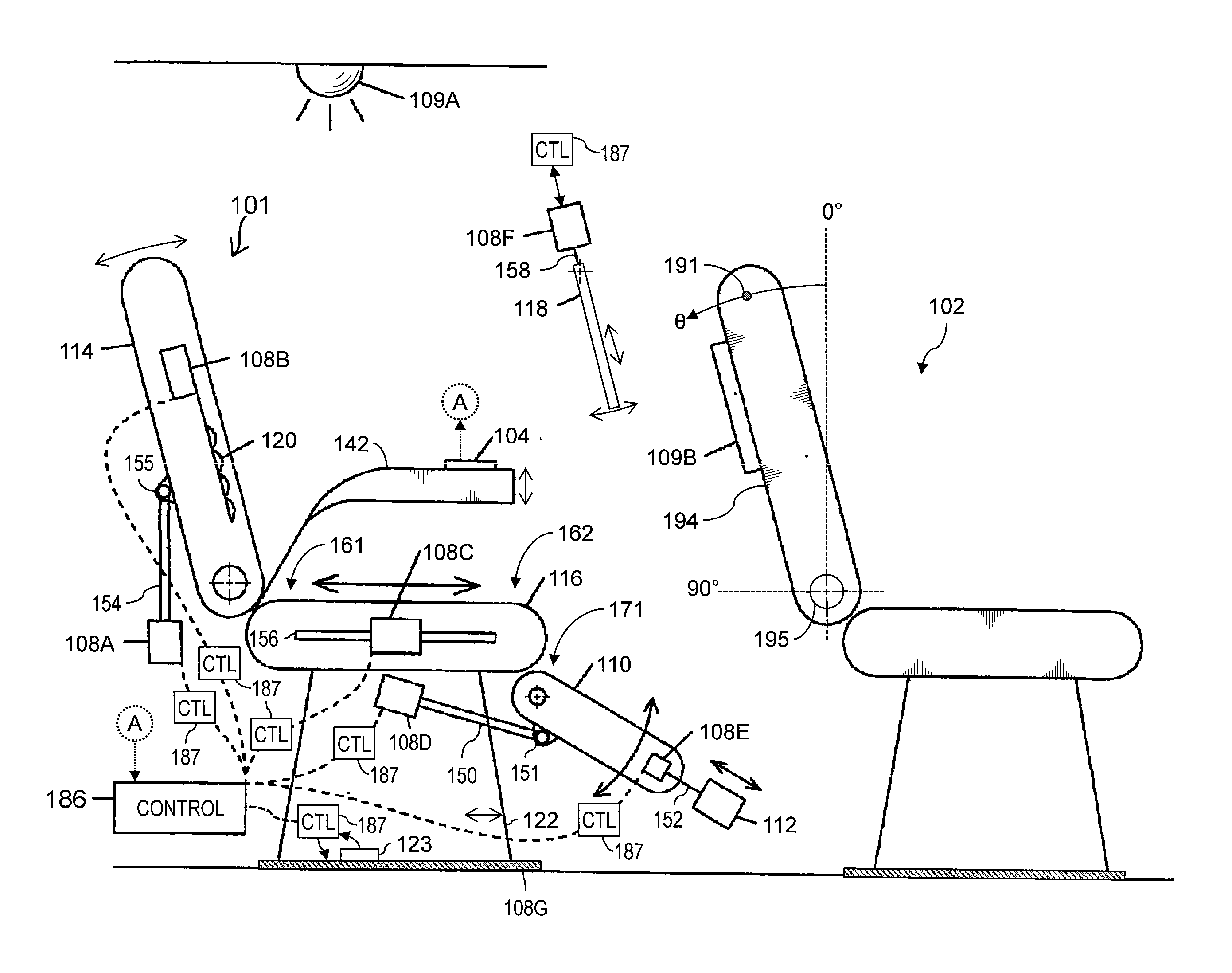
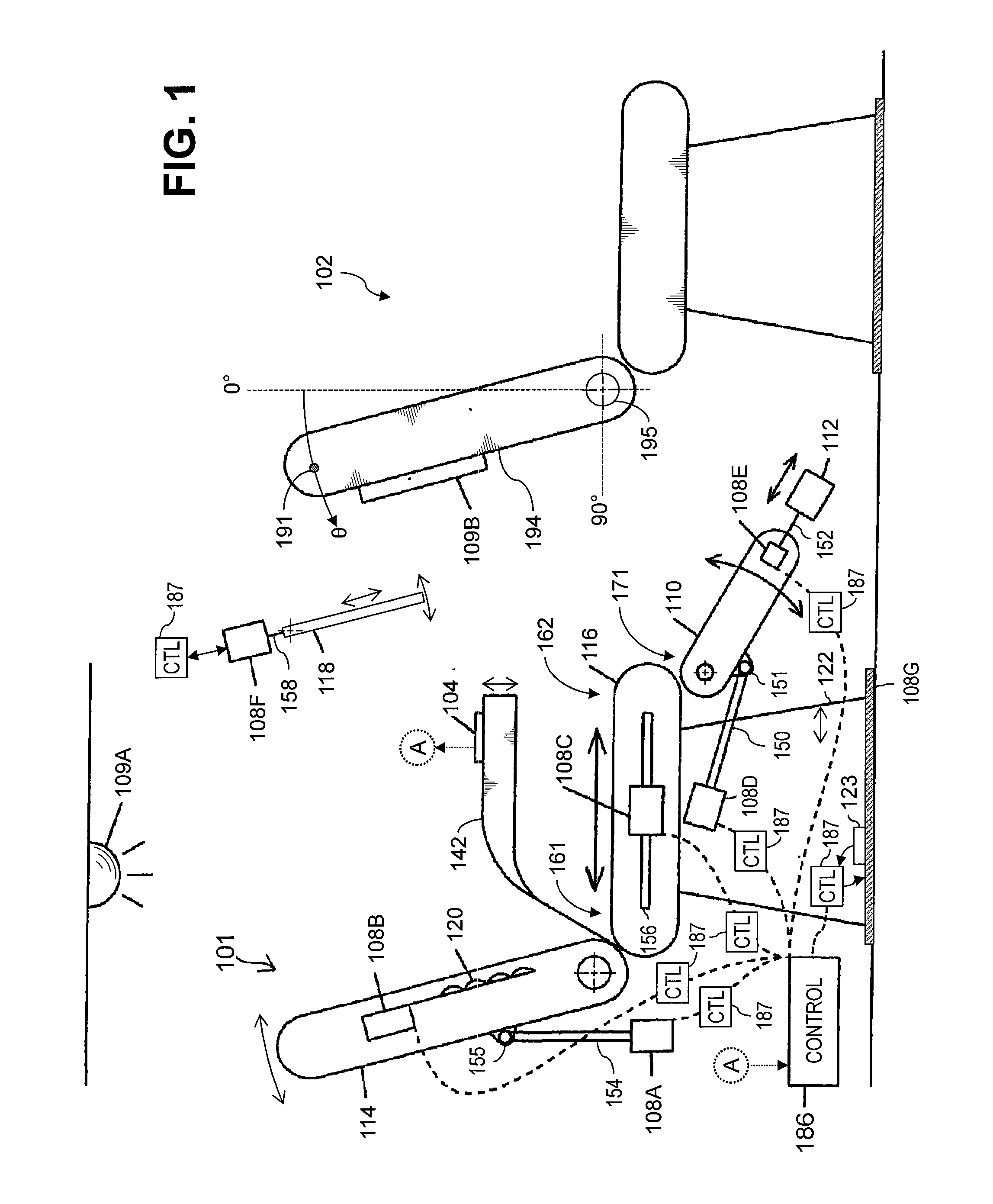
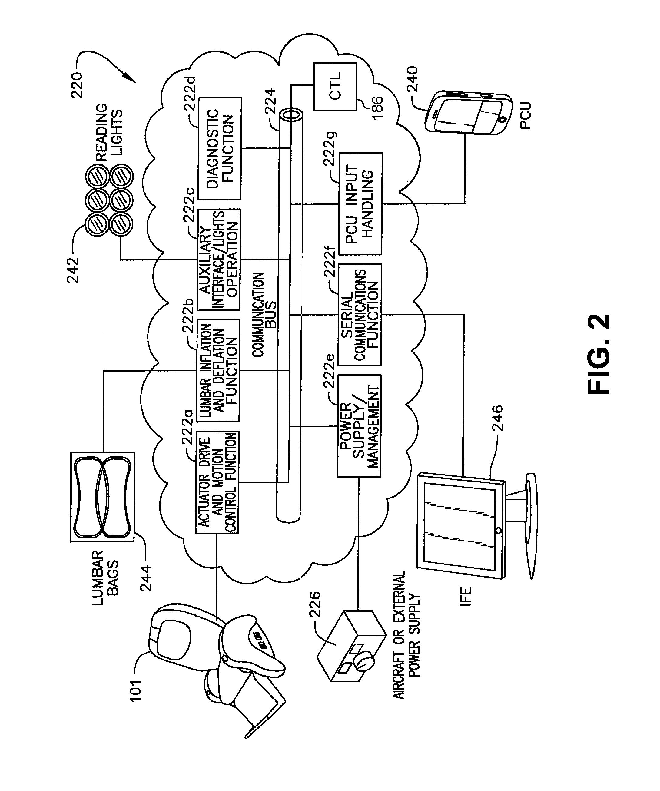
The invention relates to a method and system for controlling the motion of movable components of a powered seat in a vehicle. The system includes a controller, a sensor unit, and an actuator. The controller uses the sensor unit to monitor the feedback signal of the actuator during the motion of the components. It automatically detects the reference state of the motion command and determines the feedback-signal acceptance range during the acceleration phase of the motion. The controller then automatically stops the motion of the components if the feedback signal departs from the range during the steady-state phase of the motion. This allows for effective detection of obstructions and termination motion of the seat component, regardless of the load or non-idealities of the motion system. The invention improves the accuracy and efficiency of the powered seat control system.

Problems solved by technology

However, this system requires the incorporation of additional sensors, which add weight and potential failure modes.
Particularly for aviation uses, extra weight is undesirable.
This difference can confound schemes such as those noted above that simply use actuator current to detect obstructions.
Moreover, unoccupied seats being moved automatically or by cabin personnel can participate in obstructions with respect to nearby bulkheads or seats.
This difference is especially significant because many mechanical designs of powered seat actuators are nonlinear in behavior over their range of motion.
Various prior schemes are not capable of taking such nonlinear behavior into account.
However, Rumney does not describe detection of obstructions.

Method used


Image

  • Powered seat and control thereof
  • Powered seat and control thereof
  • Powered seat and control thereof

Examples


Embodiment Construction

[0039]Throughout this description, some embodiments are described in terms that would ordinarily be implemented as software programs. Those skilled in the art will readily recognize that algorithms according to various embodiments described herein may be embodied as systems or methods, and that the equivalent of such software can also be constructed in hardware, firmware, micro-code, or any combination of those. Because data-manipulation algorithms and systems are well known, the present description is directed in particular to algorithms and systems forming part of, or cooperating more directly with, systems and methods described herein. Other aspects of such algorithms and systems, and hardware or software for producing and otherwise processing signals or data involved therewith, not specifically shown or described herein, are selected from such systems, algorithms, software components, and elements known in the art. Given the systems and methods as described herein, software not ...


PUM


Abstract

A method of controlling motion of movable components of a powered seat includes, using the controller, monitoring a feedback signal of an actuator during motion of a component. During an acceleration phase of the motion of the component, a reference state of the time-varying motion command is detected and a reference value of the monitored feedback signal is determined as a reference value. A feedback-signal acceptance range is determined using the reference value of the monitored feedback signal. During a steady-state phase of the motion, the motion of the component is terminated if the monitored feedback signal departs the determined feedback-signal acceptance range. A control system for a powered seat of a vehicle is described. A powered seat assembly is described.

Description

TECHNICAL FIELD[0001]The present application generally relates to powered seats, and more particularly, to an actuation control system for aircraft seats.BACKGROUND[0002]Modern airplane seats, and, in particular, seats in the premium sections of a passenger airplane such as first class, are powered by actuators that enable portions of the seat to be selectively adjustable between a number of seating positions. The range of these positions may vary. For example, some powered seats may be adjustable between an upright position and a reclined position, while other seats can recline to a substantially flat position in order to function as a bed. Additionally, some airplane seats have a head rest and a foot rest that can be separately adjusted to provide a comfortable seating position. The various adjustable features of the seat are accessible and controllable using a passenger control unit, some of which may include a touchscreen or a keyboard with a display.[0003]In use and given the c...

Claims


Application Information

Patent Timeline
Patent Type & Authority Applications(United States)
IPC IPC(8): B64D11/06B60N2/75B60N2/90
CPCB60N2002/924B60N2/919B60N2/995B60N2/929B60N2/933B60N2/665B64D11/0639B64D11/064B60N2/62B60N2/66B60N2/02B60N2/0232B60N2/0244B60N2/06B60N2/16B60N2/22B60N2002/0268B60N2002/0272B60N2/986B60N2/77B60N2/809B60N2/0272B60N2/0268B60N2/02246B60N2210/14B60N2230/10
Inventor FISCHER, BRIANMCINTYRE, STEPHENMATUSEK, ROBERT D.
Owner ITT MFG ENTERPRISES LLC
Learn More