
Time varying control of the operation of spray systems

Active Publication Date: 2015-12-31
DEERE & CO
View PDF10 Cites 63 Cited by
  • Summary
  • Abstract
  • Description
  • Claims
  • Application Information

AI Technical Summary

Benefits of technology

The patent describes a sprayer system that has the ability to control the release of liquid droplets from different nozzle bodies. These nozzle bodies have different types of tips and can be adjusted through an electronic signal to produce a wider range of spray performance. This allows for better control of the fluid droplet size and improved performance at different speeds. The nozzle bodies can be mounted on agricultural or industrial spray booms and can be controlled using time-sequencing or physical configurations. The technical effect of this patent is a sprayer system that can produce a wider range of spray performance with improved control over the fluid droplet size.

Problems solved by technology

Since then, this technique has remained largely the same or unused because it results in spotty spray patterns due to long dead times, which creates problems in an agricultural setting (e.g. crops, plants, trees, vegetables, winery), where sprayers are used to apply nutrients, herbicides, insecticides and water.
Sometimes the activity of more than one hundred nozzles is coordinated, which makes PWM control complex.

Method used


Image

  • Time varying control of the operation of spray systems
  • Time varying control of the operation of spray systems
  • Time varying control of the operation of spray systems

Examples


example modes 9 and 10

[0120]Example Modes 9 and 10 include spraying using only one of the multiple valves for pulsing. For instance, this is achieved by spraying through a combined outlet as in Mode 9 or through individual outlets as in Mode 10.

[0121]Example Modes 11 through 18 are similar to Modes 1 through 8 except that the valves are spraying through individual outlets. In an embodiment with three or more valves, one way to release spray fluid is through a combined outlet and also an individual outlet, at the same time (e.g. valve 1 and 2 allow spraying through a combined outlet while valve 3 sprays through an individual outlet). For example, Modes 13 and 17 involve exercising both individual outlets, where each outlet 40 and 42 is associated with its own fluid release valve 30 and 32, respectively, in a physical configuration including nozzle 2C (FIG. 5). Valves 30 and 32 may be pulsed in phase or out of phase, but they are actuated with the same frequency or pulse width duration. The pulse width is ...


PUM


Abstract

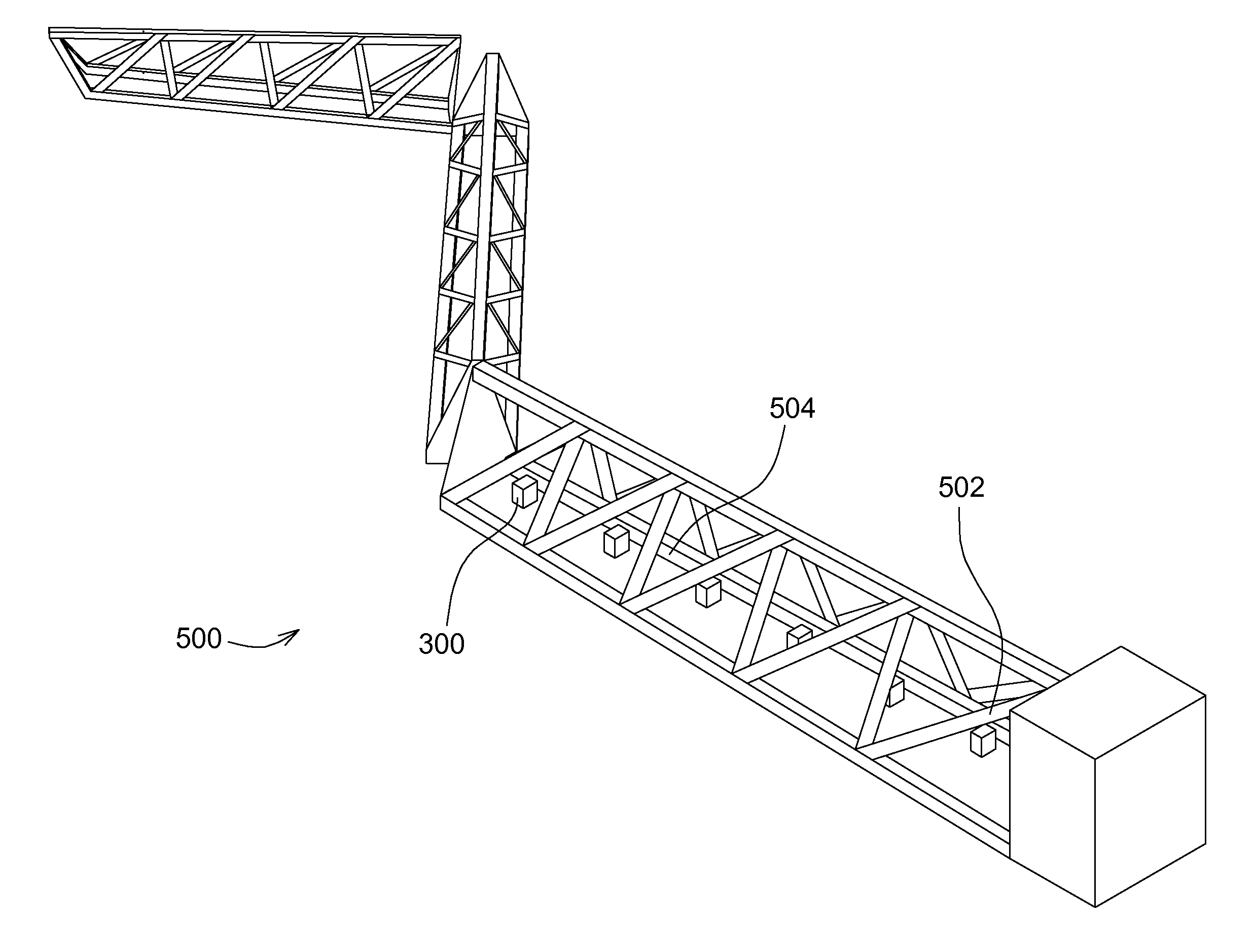
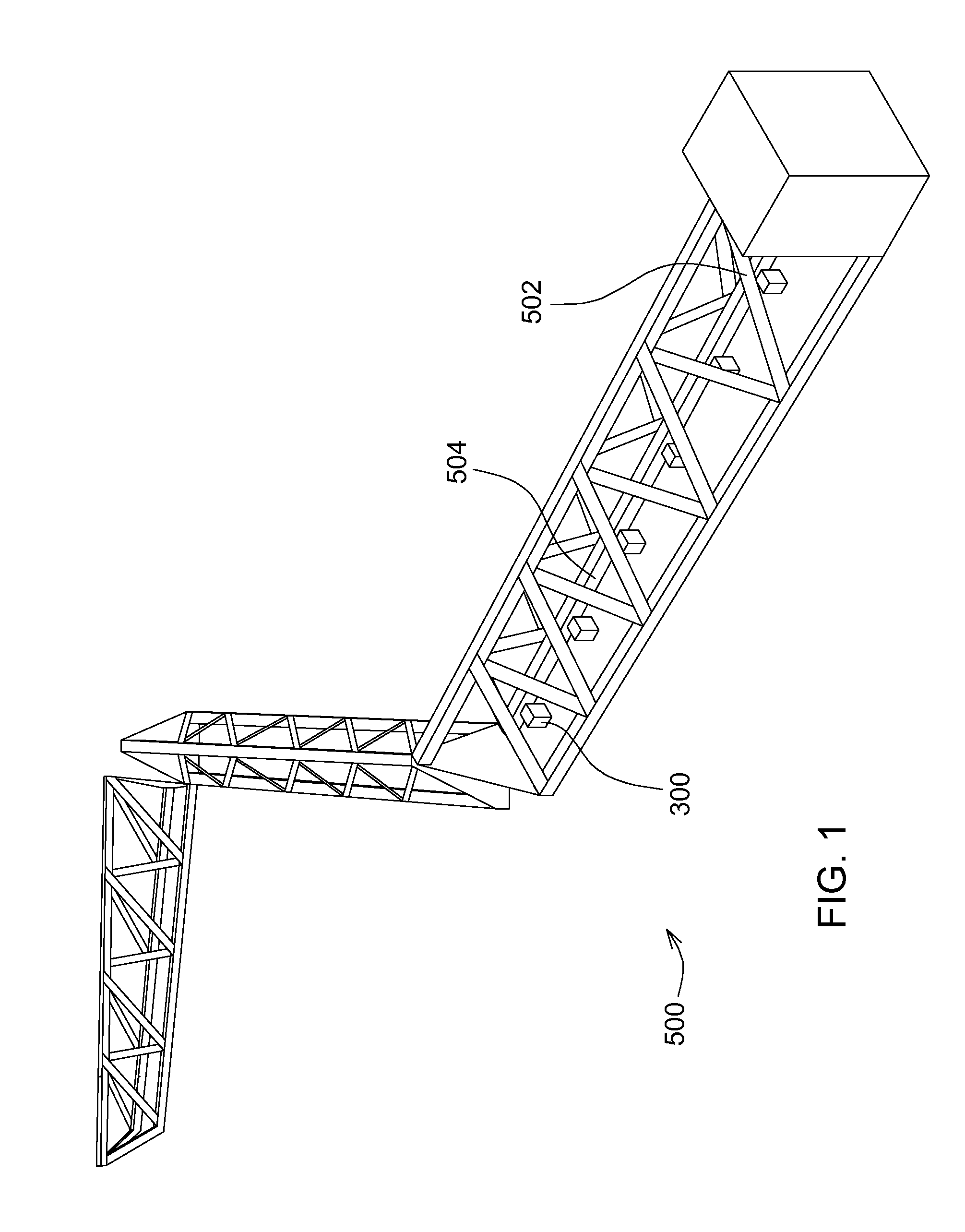
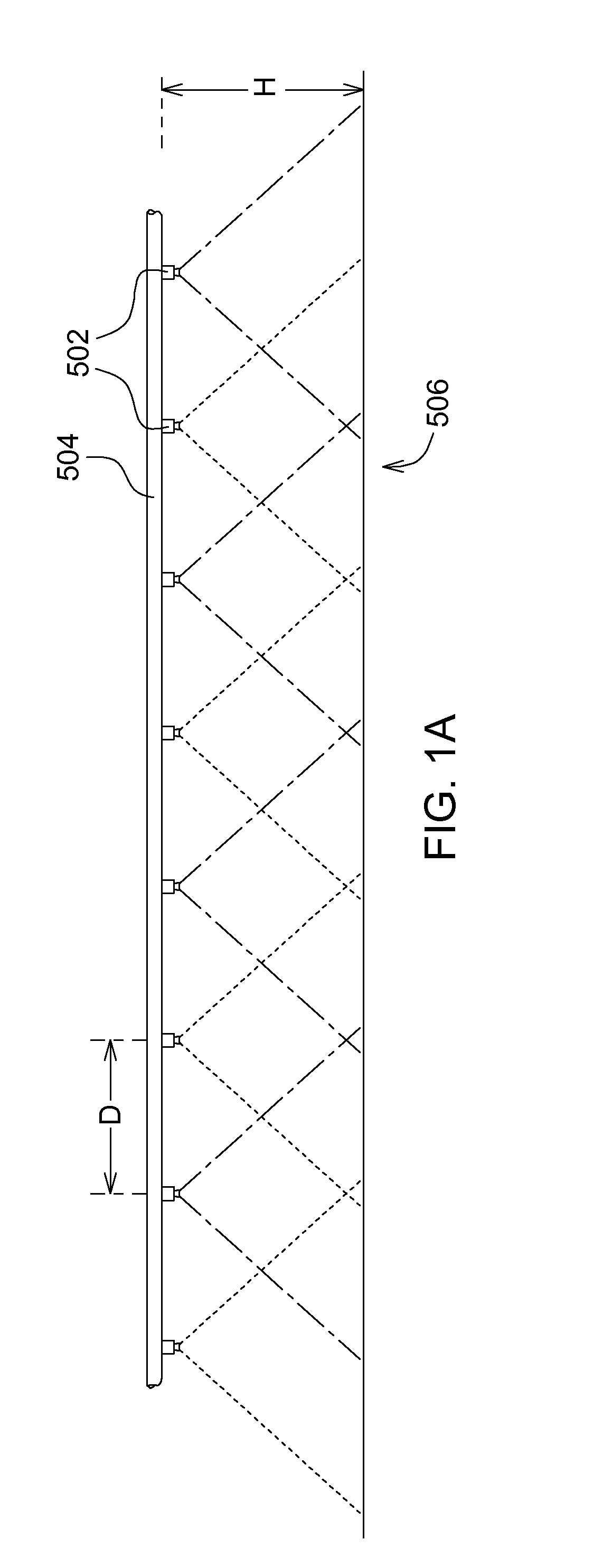
Embodiments include a sprayer system having dynamic pre-sets to control spray nozzles that each individually operates continuously or under a time-modulated or a frequency-modulated electronic signal control to release the liquid droplets. Collectively, adjacent or near neighboring nozzles are also controlled by time-sequencing through different modes of operation or physical configurations on each spray nozzle. The spray nozzles are mounted on a variety of implements including agricultural or industrial spray booms.

Description

RELATED APPLICATIONS[0001]This patent application is a continuation-in-part of U.S. patent application Ser. No. 14 / 506,057, filed Oct. 3, 2014, and entitled, HYBRID FLOW NOZZLE AND CONTROL SYSTEM, which claims priority to U.S. Provisional Patent Application Ser. No. 62 / 015,315 also entitled HYBRID FLOW NOZZLE AND CONTROL SYSTEM, both the contents of which are incorporated herein by reference. This patent application claims priority to U.S. patent application Ser. No. 14 / 505,944, filed Oct. 3, 2014, and entitled, BROADBAND SPRAY NOZZLE SYSTEMS AND METHODS, the contents of which are incorporated herein by reference. This patent application also claims priority to U.S. Provisional Patent Application Ser. No. 62 / 050,530, filed Sep. 15, 2014, and entitled, TIME VARYING CONTROL OF THE OPERATION OF SPRAY SYSTEMS, the contents of which are incorporated herein by reference.FIELD OF THE DISCLOSURE[0002]This disclosure relates generally to the control system of liquid spraying systems.BACKGROU...

Claims


Application Information

Patent Timeline
IPC IPC(8): B05B12/04B05B12/08B05B1/30
CPCB05B12/04B05B1/30B05B12/085B05B1/083B05B1/1645B05B15/658B05B1/20B05B1/3053B05B12/06A01M7/0089B05B1/169
Inventor FUNSETH, TRAVIS G.HUMPAL, RICHARD A.BULLOCK, STACY L.
Owner DEERE & CO
Learn More