
Physical Quantity Sensor Apparatus, Altimeter, Electronic Apparatus, And Moving Object

a technology of physical quantity and sensor apparatus, applied in the direction of fluid pressure measurement, fluid pressure measurement by electric/magnetic elements, instruments, etc., can solve the problems of inability to perform highly accurate temperature compensation and temperature measurement section cannot accurately perform temperature measurement of pressure sensor apparatus. , to achieve the effect of high reliability

Inactive Publication Date: 2015-12-24
SEIKO EPSON CORP
View PDF15 Cites 22 Cited by
  • Summary
  • Abstract
  • Description
  • Claims
  • Application Information

AI Technical Summary

Benefits of technology

This patent describes a sensor device that can accurately measure temperature, even at extreme temperatures. This sensor device can be used in things like altimeters and pressure sensors. The invention also provides a way to make sure the sensor is reliable and accurate, which can improve the performance and reliability of the overall device.

Problems solved by technology

Therefore, the temperature measuring section cannot accurately perform temperature measurement of the pressure sensor apparatus (in particular, the diaphragm section).
Therefore, highly accurate temperature compensation cannot be performed.

Method used


Image

  • Physical Quantity Sensor Apparatus, Altimeter, Electronic Apparatus, And Moving Object
  • Physical Quantity Sensor Apparatus, Altimeter, Electronic Apparatus, And Moving Object
  • Physical Quantity Sensor Apparatus, Altimeter, Electronic Apparatus, And Moving Object

Examples


first embodiment

1. Physical Quantity Sensor Apparatus

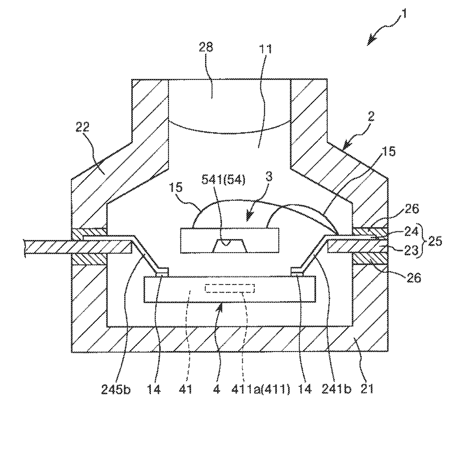
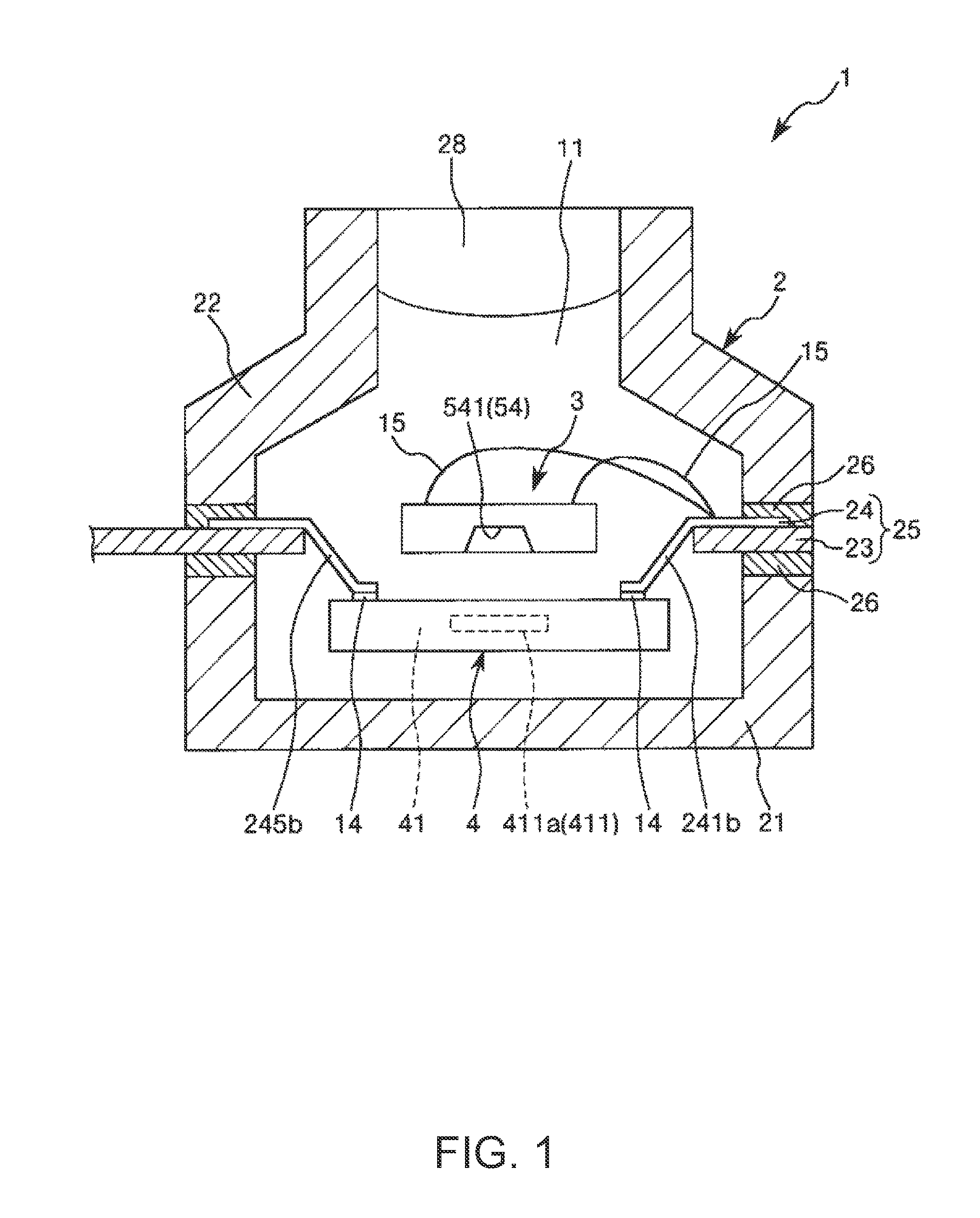
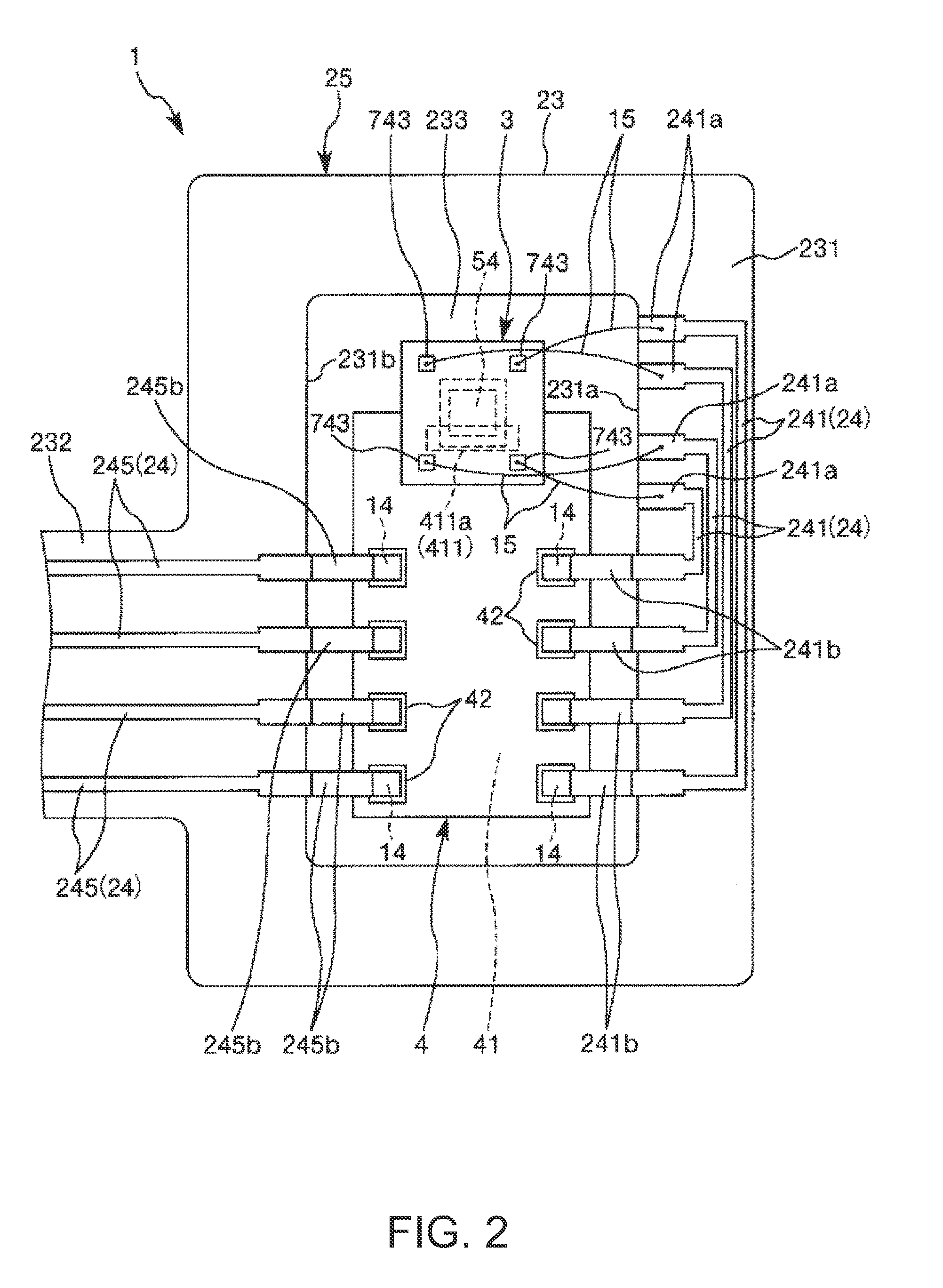
[0040]FIG. 1 is a sectional view showing a physical quantity sensor apparatus according to a first embodiment of the invention. FIG. 2 is a plan view of the physical quantity sensor apparatus shown in FIG. 1. FIG. 3 is a sectional view showing a physical quantity sensor included in the physical quantity sensor apparatus. FIG. 4 is a plan view showing a pressure sensor section included in the physical quantity sensor shown in FIG. 3. FIG. 5 is a diagram showing a circuit including the pressure sensor section shown in FIG. 4. Note that, in the following explanation, the upper side in FIGS. 1 and 3 is referred to as “upper” and the lower side in FIGS. 1 and 3 is referred to as “lower”.

[0041]A pressure sensor apparatus (a physical quantity sensor apparatus) 1 shown in FIG. 1 includes a pressure sensor (a physical quantity sensor) 3, an IC chip 4 electrically connected to the pressure sensor 3 and including a temperature sensor 411, a package 2 that h...

second embodiment

[0078]FIG. 6 is a plan view showing a physical quantity sensor apparatus according to a second embodiment of the invention.

[0079]The physical quantity sensor apparatus according to the second embodiment is explained below. Differences from the first embodiment are mainly explained. Explanation of similarities is omitted.

[0080]The second embodiment is the same as the first embodiment except that the disposition and a connection method of a pressure sensor and an IC chip are different.

[0081]As shown in FIG. 6, in the pressure sensor apparatus 1 in this embodiment, both the ends of the wiring sections 241 are located on the frame section 231. That is, unlike the first embodiment, one ends of the wiring sections 241 are not formed as flying leads. The entire pressure sensor 3 is disposed to overlap the IC chip 4 in plan view. In other words, the entire pressure sensor 3 is included in the IC chip 4 in plan view. The IC chip 4 is connected to the wiring sections 241 and 245 via bonding w...


PUM


Abstract

A physical quantity sensor apparatus includes a physical quantity sensor including a flexurally deformable diaphragm including a pressure receiving surface and a temperature sensor disposed on the pressure receiving surface side of the diaphragm to be spaced apart from the diaphragm. The pressure sensor includes a hollow section, which is a pressure reference chamber, on a surface side opposite to the pressure receiving surface of the diaphragm.

Description

CROSS REFERENCE[0001]This application claims benefit of Japanese Application No. 2014-125089, filed on Jun. 18, 2014. The disclosure of the prior application is hereby incorporated by reference herein in its entirety.BACKGROUND[0002]1. Technical Field[0003]The present invention relates to a physical quantity sensor apparatus, an altimeter, an electronic apparatus, and a moving object.[0004]2. Related Art[0005]For example, a pressure sensor module described in JP-A-2013-164332 (Patent Literature 1) includes a pressure sensor apparatus including a diaphragm section and configured to detect pressure on the basis of deflection of the diaphragm section and a temperature compensating apparatus including a temperature measuring section (a temperature sensor section). The pressure sensor section and the temperature measuring section are thermally connected via a heat transfer wire. Therefore, it is possible to perform temperature compensation for the detected pressure on the basis of the te...

Claims


Application Information

Patent Timeline
IPC IPC(8): G01L9/06G01C5/06
CPCG01C5/06G01L9/065G01L9/0042G01L9/0054G01L19/0084G01L19/0654G01L19/143H01L2224/48091H01L2924/00014
Inventor NAKAJIMA, SATOSHI
Owner SEIKO EPSON CORP
Learn More