Electromechanical actuator and home automation installation comprising such an actuator

a technology of electromechanical actuators and actuators, which is applied in the direction of dynamo-electric machines, curtain suspension devices, building components, etc., can solve the problems of reducing affecting the acoustic level of electromechanical actuators, and the output member and the inner friction surface of the drum housing are detrimental to the electromechanical level. , to achieve the effect of reducing friction nois

Inactive Publication Date: 2015-12-17
SOMFY SAS
View PDF4 Cites 8 Cited by
  • Summary
  • Abstract
  • Description
  • Claims
  • Application Information

AI Technical Summary

Benefits of technology

The present invention proposes an electromechanical actuator with a spring-loaded brake that reduces friction noises during rotational driving of the input member and / or the output member inside the housing of the drum. This is achieved through the use of a ring positioned between the outer surface of the input member and / or the output member and the inner friction surface of the housing of the drum. The ring prevents direct contact between the input / output member and the inner friction surface of the housing, thereby reducing rubbing noises and avoiding misalignment flaws that could create operating noises of the spring-loaded brake.

Problems solved by technology

However, this electromechanical actuator has the drawback of creating friction noises related to the rubbing of an outer surface of the input member and / or the output member against the inner friction surface of the housing of the drum.
The unwanted friction between the outer surface of the input member and / or the output member and the inner friction surface of the housing of the drum during rotational driving of the input member and / or the output member inside the housing of the drum is caused by an alignment flaw of the input member and / or the output member relative to the axis of rotation of the spring-loaded brake.
Consequently, such rubbing between the outer surface of the input member and / or the output member and the inner friction surface of the housing of the drum is detrimental to the acoustic level of the electromechanical actuator during its operation.

Method used


Image

  • Electromechanical actuator and home automation installation comprising such an actuator
  • Electromechanical actuator and home automation installation comprising such an actuator
  • Electromechanical actuator and home automation installation comprising such an actuator

Examples


Embodiment Construction

[0045]In reference to FIGS. 1 and 2, we will first describe a home automation installation according to the invention and installed in a building comprising an opening 1, window or door, equipped with a screen 2 belonging to a concealing device 3, in particular a motorized rolling shutter.

[0046]The concealing device 3 can be a rolling shutter, as illustrated in FIGS. 1 and 2, a canvas blind or blinds with adjustable slats, or a rolling gate. The present invention applies to all types of concealing devices.

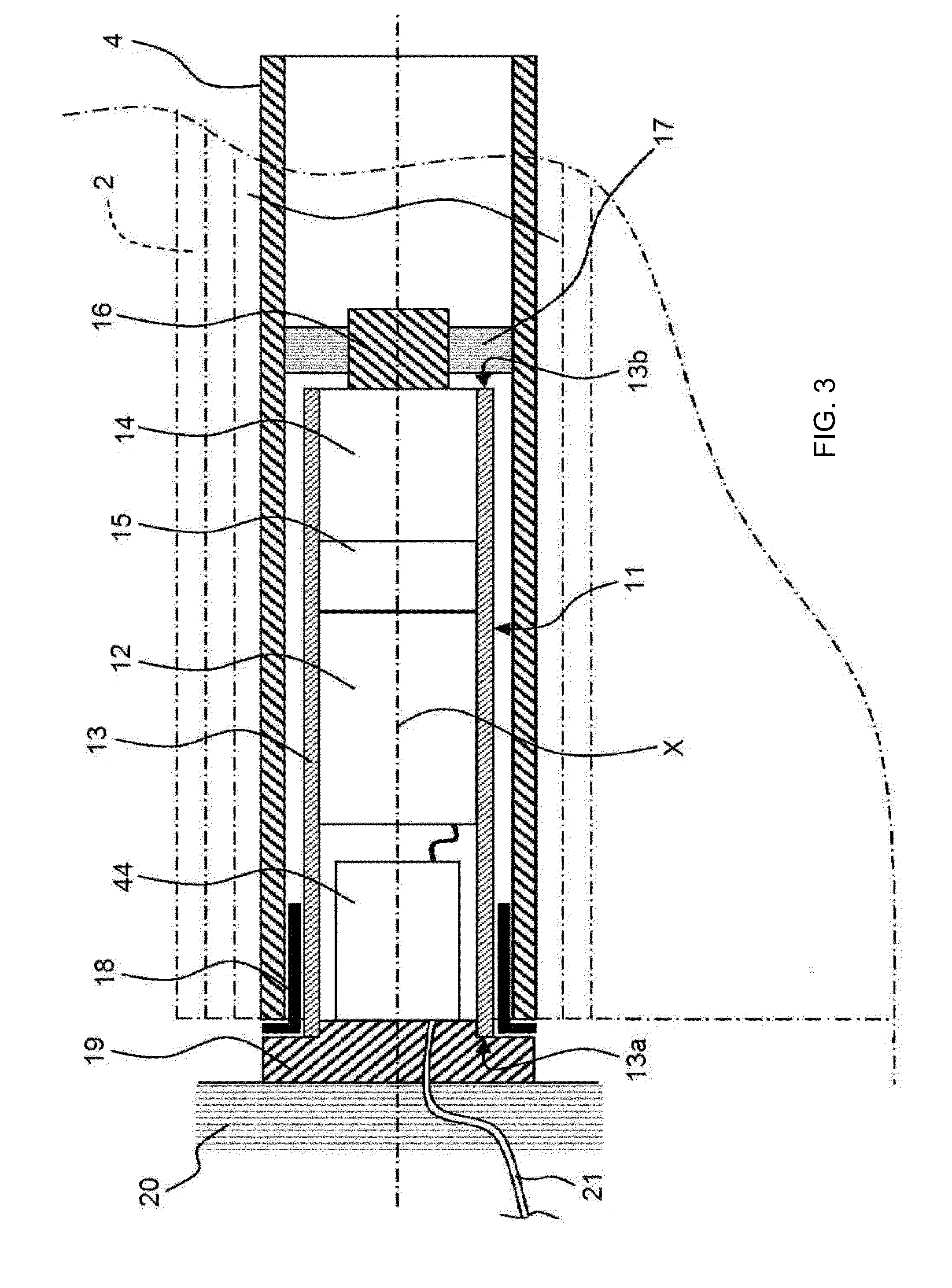
[0047]The screen 2 of the concealing device 3 is wound on a winding tube 4 driven by a motorized driving mechanism 5 and movable between a wound position, in particular an upper position, and an unwound position, in particular a lower position.

[0048]The motorized driving mechanism 5 comprises an electromechanical actuator 11, in particular of the tubular type, making it possible to set the winding tube 4 of the concealing device 3 in rotation so as to unwind or wind the screen 2 of...


PUM


Abstract

An electromechanical actuator for a home automation closing or sun protection installation includes an electric motor, a reduction gear and a spring-operated brake (15), which includes a helical spring (22), a drum (23), an input member (24) and an output member (25). The drum (23) includes a housing (26). An inner friction surface (27) of the housing (26) of the drum (23) cooperates with at least one turn of the helical spring (22). The spring-operated brake (15) also includes at least one ring (50) positioned between an outer surface (51) of the input member (24) and / or the output member (25) and the inner friction surface (27) of the housing (26) of the drum (23). The home automation installation includes one such actuator.

Description

FIELD OF THE INVENTION[0001]The present invention relates to an electromechanical actuator. The electromechanical actuator comprises a spring-loaded brake. This type of spring-loaded brake is more particularly suitable for a so-called tubular electromechanical actuator.[0002]The present invention also relates to a home automation installation for closing or sun protection comprising a screen able to be wound on a winding tube rotated by one such electromechanical actuator.[0003]In general, the present invention relates to the field of concealment devices comprising a motorized driving device setting a screen in motion between at least one first position and one second position.BACKGROUND OF THE INVENTION[0004]A motorized driving device comprises an electromechanical actuator for a movable element for closing, concealing or providing sun protection such as a shutter, door, grate, blind, or any other equivalent material, hereinafter referred to as a screen.[0005]Document FR 2,610,668 ...

Claims


Application Information

Patent Timeline
IPC IPC(8): H02K7/102E06B9/68E06B9/72H02K7/116
CPCH02K7/102H02K7/116E06B2009/725E06B9/72E06B9/68E06B9/322E06B9/88E06B9/90E06B2009/905
Inventor BRONDEX, ADRIEN
Owner SOMFY SAS
Why Eureka
Try Eureka