
Single action locking pedicle screwdriver

Active Publication Date: 2015-12-17
ALPHATEC SPINE INC
View PDF10 Cites 16 Cited by
  • Summary
  • Abstract
  • Description
  • Claims
  • Application Information

AI Technical Summary

Benefits of technology

[0009]The instrument can also include a screw jaw assembly tensioner that is operable to pull on the screw jaw assembly in a direction towards the housing and away from the distal end of the driver shaft. The pull or force on the screw jaw assembly in the direction towards the housing ensu

Problems solved by technology

Specifically, one hand supports the driver while the other hand rotates a sleeve in a l

Method used


Image

  • Single action locking pedicle screwdriver
  • Single action locking pedicle screwdriver
  • Single action locking pedicle screwdriver

Examples


Embodiment Construction

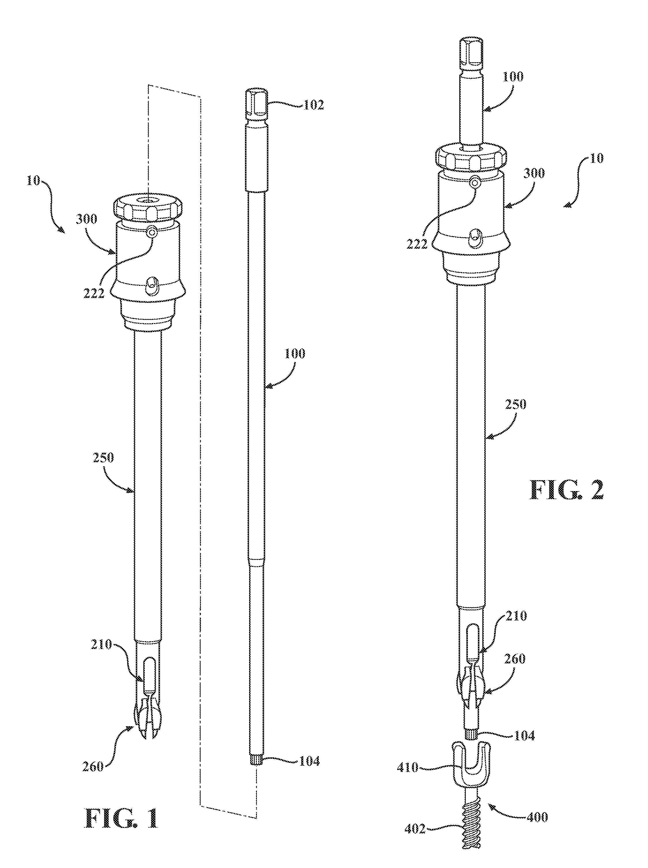
[0024]An instrument 10 that simplifies secure attachment of a screw assembly using a single-action locking mechanism 500 actuated by a distal advancement of the instrument 10 is provided. As such, attachment, locking and alignment of a screw assembly 400 to the instrument 10 is accomplished by simply thrusting the end of the instrument 10 into the head 404 of the screw assembly 400 and wherein the thrust not only locks the instrument to the screw assembly, but may also generate a preload condition within the screw assembly 400.

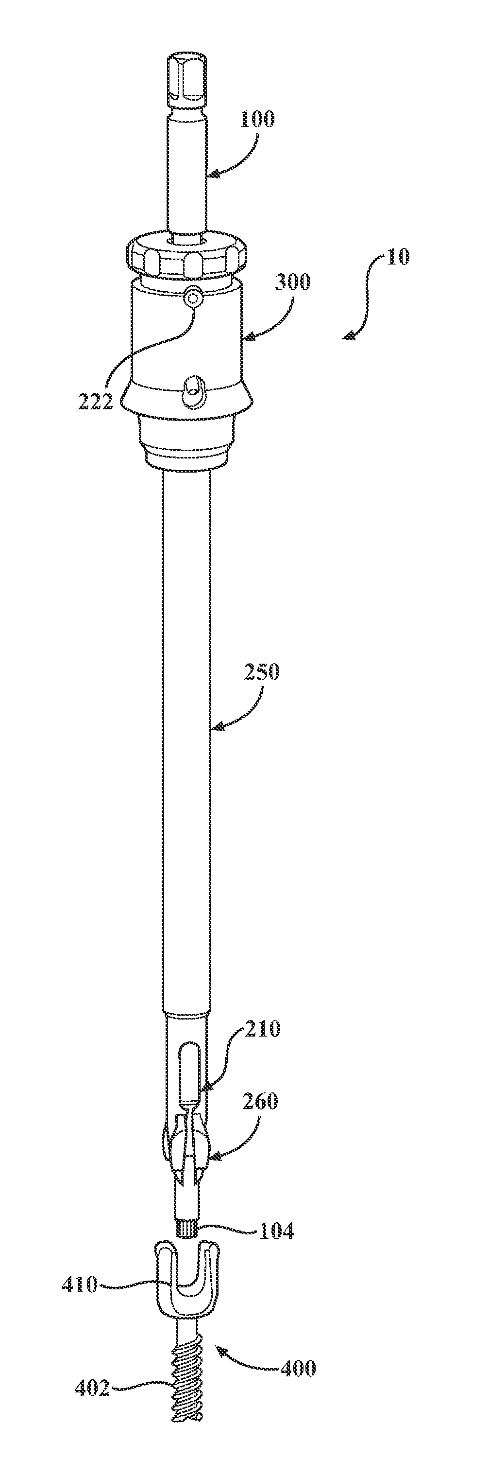
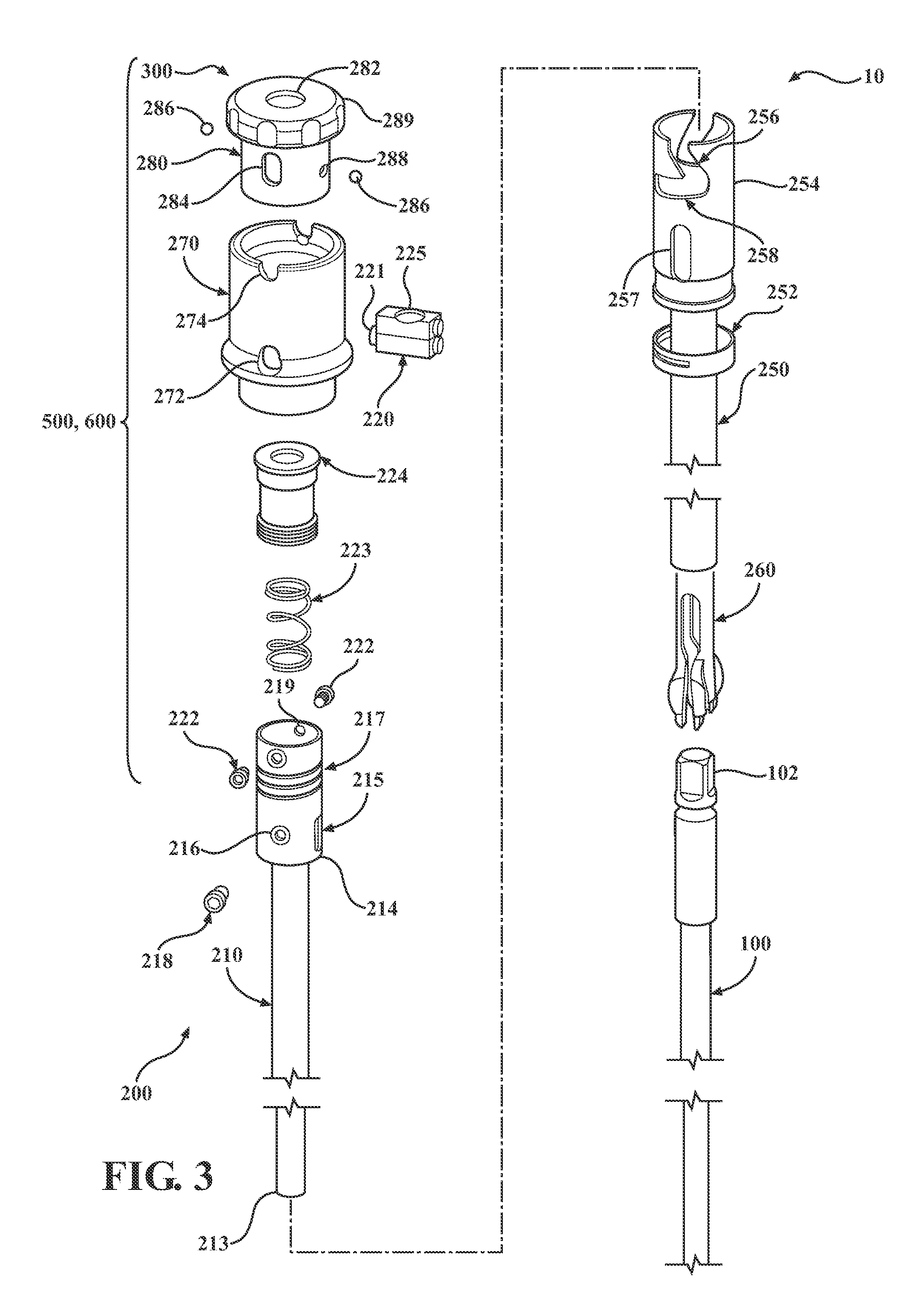
[0025]Turning now to FIG. 1, an embodiment of the instrument 10 is shown at reference numeral 10. The instrument 10 has a main shaft 250 having a locking tube 210, a housing 300, and a driver shaft 100. The driver shaft 100 has a distal end 104 opposite a proximal end 102. In addition, a handle known to those skilled in the art (not shown) can be attached to the proximal end 102 in order to assist a surgeon rotating the driver shaft 100. The main shaft 250 is ...


PUM


Abstract

An instrument for attaching a driver shaft to a screw assembly using a thrusting motion. The instrument has a main shaft, a locking tube, and a driver shaft. The locking tube is slidably mounted within the main shaft and the driver shaft is slidably mounted within the locking tube. The locking tube is configured to urge a jaw assembly of the instrument into a tensioned engagement with a body member of the screw assembly. A locking mechanism is also included and is configured to lock the driver shaft in a fixed position relative to the locking tube. The locking mechanism may be configured to lock the driver shaft with respect to the locking tube after a distal end of the main shaft engages the screw assembly using the single action.

Description

FIELD OF THE INVENTION[0001]The present invention is related to a medical instrument and in particular to a medical instrument for attaching a driver shaft to a screw assembly using a single action.BACKGROUND OF THE INVENTION[0002]Instruments for screwing or driving screws into bone material are known. The screws are typically presented to the surgeon in a tray, wherein the heads of the screw are exposed. To maintain a sterile environment, the heads of the screw are configured to engage the instrument. Accordingly, the surgeon stabs the head of the screw with an end of the instrument to engage the screw head in a temporary setting, and then must secure the head to the instrument. Current instruments require two hands to perform such an act. One hand is used to engage the head in a temporary setting. However a second hand is needed to secure the head of the screw to the instrument. Specifically, one hand supports the driver while the other hand rotates a sleeve in a labor intensive a...

Claims


Application Information

Patent Timeline
IPC IPC(8): A61B17/70
CPCA61B17/7032A61B17/7082
Inventor REIMELS, WILLIAMSTEVENSON, TARA
Owner ALPHATEC SPINE INC
Learn More