
Organic electroluminescent display device

an electroluminescent display and electroluminescent technology, applied in the direction of organic semiconductor devices, solid-state devices, thermoelectric devices, etc., can solve the problems of uneven hole-injection properties of anodes, and device efficiency, and achieve the effect of longer device life and higher device efficiency

Inactive Publication Date: 2015-12-10
JAPAN DISPLAY INC
View PDF8 Cites 4 Cited by
  • Summary
  • Abstract
  • Description
  • Claims
  • Application Information

AI Technical Summary

Benefits of technology

The present invention aims to improve the efficiency and lifespan of organic EL display devices that have uneven hole-injecting properties in their anode electrodes. The technical effect of this invention is to create a display device that can overcome these issues and still maintain optimal performance.

Problems solved by technology

The O2 plasma treatment, however, may cause decomposition of the materials for the circuit substrate depending on conditions and thus affect the ionization potential of the anode electrodes to result in unevenness in the hole-injecting properties of the anode electrodes.
Other factors than this may also cause unevenness in the hole-injecting properties of the anode electrodes.
The unevenness in the hole-injecting properties may reduce the device efficiency and increase the drive voltage, thus resulting in a shorter device life.

Method used


Image

  • Organic electroluminescent display device
  • Organic electroluminescent display device
  • Organic electroluminescent display device

Examples


Embodiment Construction

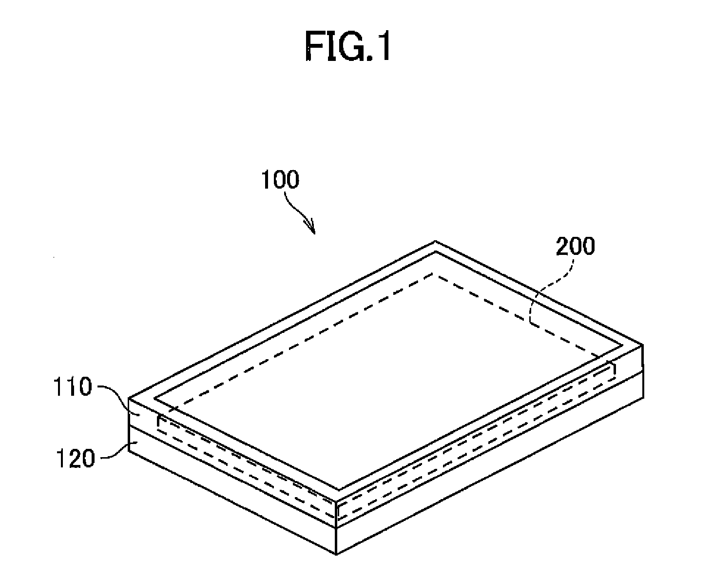
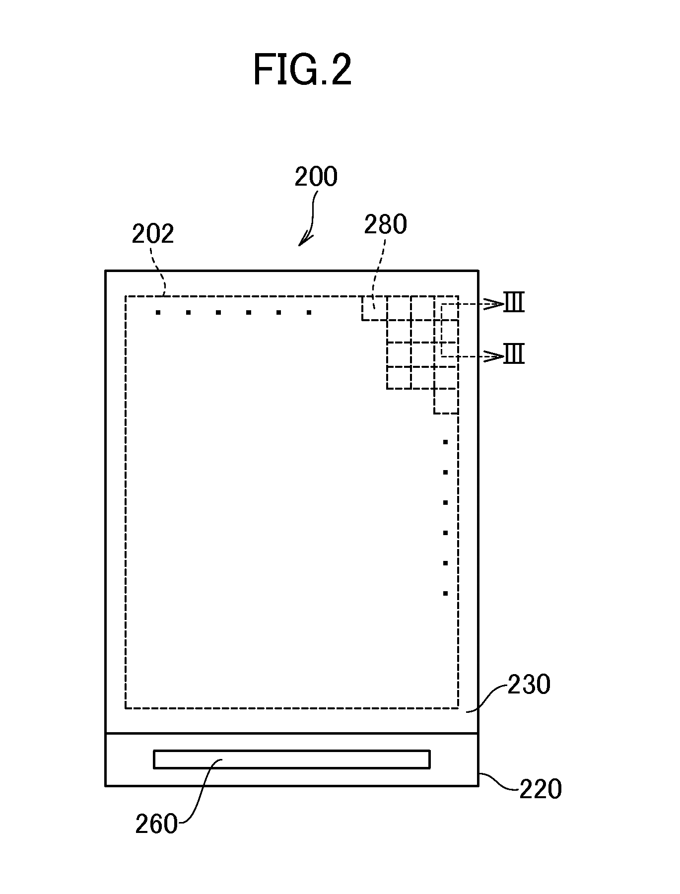
[0020]Embodiments of the present invention are described below with reference to the accompanying drawings. The disclosure herein is merely an example, and appropriate modifications coming within the spirit of the present invention, which are easily conceived by those skilled in the art, are intended to be included within the scope of the invention as a matter of course. The accompanying drawings schematically illustrate widths, thicknesses, shapes, or other characteristics of each part for clarity of illustration, compared to actual configurations. However, such a schematic illustration is merely an example and not intended to limit the present invention. In the present specification and drawings, some elements identical or similar to those shown previously are denoted by the same reference signs as the previously shown elements, and thus repetitive detailed descriptions of them may be omitted as appropriate.

[0021]FIG. 1 schematically shows an organic EL display device 100 accordin...


PUM


Abstract

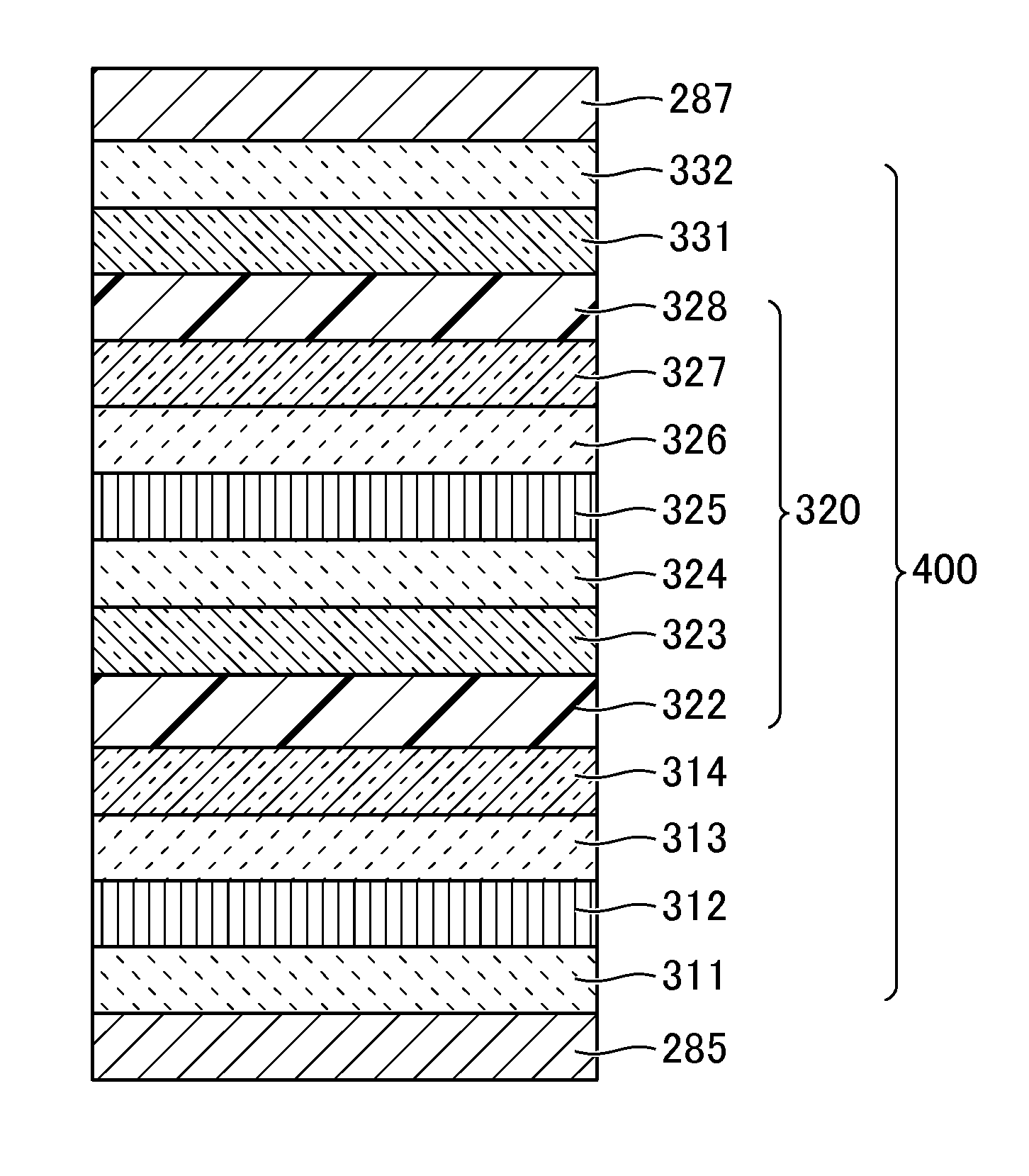
An organic EL display device includes an anode electrode made of a conductive material, a cathode electrode made of a conductive material, an anode-side electron injection layer that is an electron injection layer on the anode electrode and between the anode electrode and the cathode electrode, and an anode-side charge generation layer that is a charge generation layer on the anode-side electron injection layer.

Description

CROSS-REFERENCE TO RELATED APPLICATION[0001]The present application claims priority from Japanese application JP2014-117668 filed on Jun. 6, 2014, the content of which is hereby incorporated by reference into this application.BACKGROUND OF THE INVENTION[0002]1. Field of the Invention[0003]The present invention relates to an organic electroluminescent (EL) display device.[0004]2. Description of the Related Art[0005]In recent years, image display devices including a self-luminous element called an organic light-emitting diode, hereinafter simply “organic EL display devices”, have been in practical use. Such an organic EL display device with a self-luminous element is excellent in visibility and response speed compared with liquid crystal display devices known in the art. Additionally, the organic EL display device eliminates the need for an auxiliary lighting device, such as a backlight, and thus can be made thinner.[0006]JP 2006-049906 A discloses an organic light-emitting device tha...

Claims


Application Information

Patent Timeline
Patent Type & Authority Applications(United States)
IPC IPC(8): H01L51/50H01L51/52
CPCH01L51/5092H01L51/5206H01L51/5221H01L51/5088H01L51/5004H01L51/5012H01L51/5072H01L2251/562H01L51/5056H10K50/167H10K50/171H10K50/15H10K50/19H10K59/8051H10K59/80524H10K50/11H10K50/16H10K50/17H10K50/81H10K50/82H10K50/828H10K71/831H10K2101/40
Inventor GUNJI, MASAKAZUSATO, TOSHIHIRO
Owner JAPAN DISPLAY INC
Learn More