Apparatus and method for controlling and regulating a multi-element system

Active Publication Date: 2015-12-10
SIEMENS AG
View PDF14 Cites 16 Cited by
  • Summary
  • Abstract
  • Description
  • Claims
  • Application Information

AI Technical Summary

Benefits of technology

This patent describes a control system for a system with multiple elements that can move independently. The system uses a cascaded control approach, which allows for faster and more accurate compensation of interfering forces. The control system takes into account various factors such as the position, speed, and force of the elements to achieve precise movement in all details. The torque calculating device continuously calculates the maximum acceleration of the elements to make the most use of the current and pressure limits. Additionally, the control system and torque device work together to reduce the excitation of the system's natural frequencies, resulting in improved motion behavior.

Problems solved by technology

However, external interfering forces (for example gravitational force, process force, friction, load change, etc.) act on the mechanical structures, said forces potentially leading to deviations at the so-called “TCP” (Tool Center Point) due to the resilience of the joints and components (hereinafter also called individual elements).
The positional dependency of the deviation at the TCP is in some circumstances very high due to the interfering forces.
The use of a second measurement system is associated with considerable additional hardware costs and requires a complex adaptation of the structure in order to install the measurement system.
The drawback with this method is the effort and costs required for the measurement of the working area and / or of the robot / machine.
The counter force is based on a structure which is not infinitely rigid and may in any case cause parasitic movements at the TCP.
However, in industrial robots this value is not constant over the working area, due to the construction.
However, this requires structural boundary conditions which make the robot into a structure which is highly susceptible to vibrations.
Due to the absence of measuring options an electrical damping of these vibrations is not possible.
The drawback with this method is the necessary restriction of the axial dynamics which can be considerable.
Monitoring the measurement signals (for example the motor current) is also not possible due to the loading which can be highly variable.

Method used


Image

  • Apparatus and method for controlling and regulating a multi-element system
  • Apparatus and method for controlling and regulating a multi-element system
  • Apparatus and method for controlling and regulating a multi-element system

Examples


Embodiment Construction

[0041]Throughout all the Figures, same or corresponding elements are generally indicated by same reference numerals. These depicted embodiments are to be understood as illustrative of the invention and not as limiting in any way. It should also be understood that the drawings are not necessarily to scale and that the embodiments are sometimes illustrated by graphic symbols, phantom lines, diagrammatic representations and fragmentary views. In certain instances, details which are not necessary for an understanding of the present invention or which render other details difficult to perceive may have been omitted.

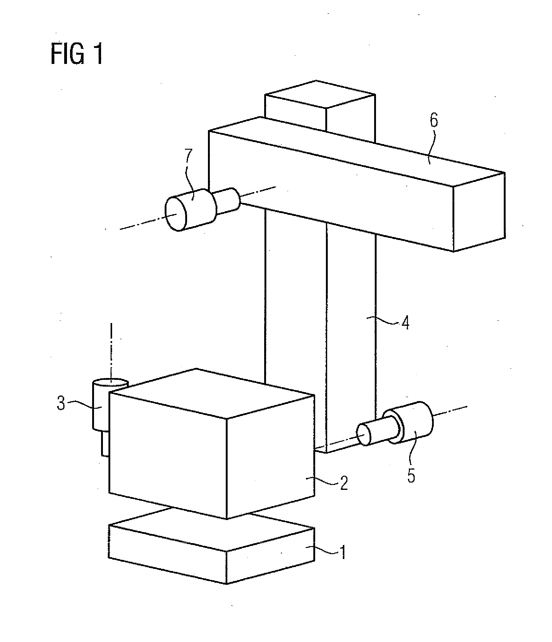
[0042]For a system of any design (machine, equipment, etc.) of the type mentioned in the introduction, in particular a robot or a machine tool, an apparatus may be used for controlling and regulating the movement of its plurality of individual elements which cooperate kinematically. An example of such a multi-element system is shown in FIG. 1. Here components of a robot are sh...


PUM


Abstract

An apparatus for controlling and regulating a movement of a system includes a load calculating device calculating continuously during the movement of the system a respective force vector for each of the individual elements as a function of predetermined reference coordinates and a torque calculating device calculating continuously during the movement at least one compensating variable, wherein the compensating variable compensates the force vectors as a function of the reference coordinates and the force vectors. The apparatus for controlling and regulating has a control unit controlling continuously during the movement a force-producing variable for the at least one drive as a function of the reference and the at least one compensating variable.

Description

CROSS-REFERENCES TO RELATED APPLICATIONS[0001]This application claims the priority of European Patent Application, Serial No. EP14171752, filed Jun. 10, 2014, pursuant to 35 U.S.C. 119(a)-(d), the disclosure of which is incorporated herein by reference.BACKGROUND OF THE INVENTION[0002]The present invention relates to an apparatus for controlling and regulating a movement of a system including a plurality of individual elements which cooperate kinematically, at least one thereof being a drive. The present invention further relates to a method for controlling and regulating a movement of such a system. Such a system is understood, for example, as equipment, a machining tool, a processing machine and, in particular, also a robot or a machine tool. The drive is, for example, an electric motor or a hydraulic or pneumatic drive.[0003]The following discussion of related art is provided to assist the reader in understanding the advantages of the invention, and is not to be construed as an a...

Claims


Application Information

Patent Timeline
IPC IPC(8): G05D17/02G05B13/04
CPCG05B13/04G05D17/02B25J9/1638G05B2219/39176G05B2219/39194G05B2219/39319
Inventor BITTEROLF, DAVIDHAMANN, JENSHAMM, CARSTENTAUCHMANN, SVEN
Owner SIEMENS AG
Why Eureka
Try Eureka