
Fixing device for sliding mechanism

Active Publication Date: 2015-12-10
JOCHU TECH
View PDF0 Cites 0 Cited by
  • Summary
  • Abstract
  • Description
  • Claims
  • Application Information

AI Technical Summary

Benefits of technology

The present invention is a slide positioning device for a sliding mechanism that includes an exterior plate, an intermediate plate connected slidably to the exterior plate, and an interior plate connected slidably to the intermediate plate. The device prevents damage to the slide positioning device when a great external force is applied. The interior plate includes a position limiting unit and an elongated release rod that can be easily manipulated to disengage the position limiting unit and allow for smooth movement between the two plates. The slide positioning device is used in a sliding mechanism and is designed to facilitate movement of the release rod and prevent untimely disengagement of the release rod from the interior plate.

Problems solved by technology

The conventional fixing device generally includes two connection rods or a spring plate and hook-and-looped fasteners and etc such that great manufacturing cost is resulted owing to too many pieces.
It is noted that in case of a great impact applied on the conventional sliding mechanism at this time, ruin of the sliding mechanism will be resulted since the plates cannot withstand the great impact.
One drawback of the above sliding mechanisms resides in that once the interior plate is pulled outward from the intermediate plate and in case of an external impact, the hook-and-looped fasteners or the locking structure are subjected to damage easily, which, in turn, leads to ruin of the sliding mechanism.

Method used


Image

  • Fixing device for sliding mechanism
  • Fixing device for sliding mechanism
  • Fixing device for sliding mechanism

Examples


Embodiment Construction

[0027]The accompanying drawings are included to provide a further understanding of the invention, and are incorporated in and constitute a part of this specification. The drawings illustrate embodiments of the invention and, together with the description, serve to explain the principles of the invention.

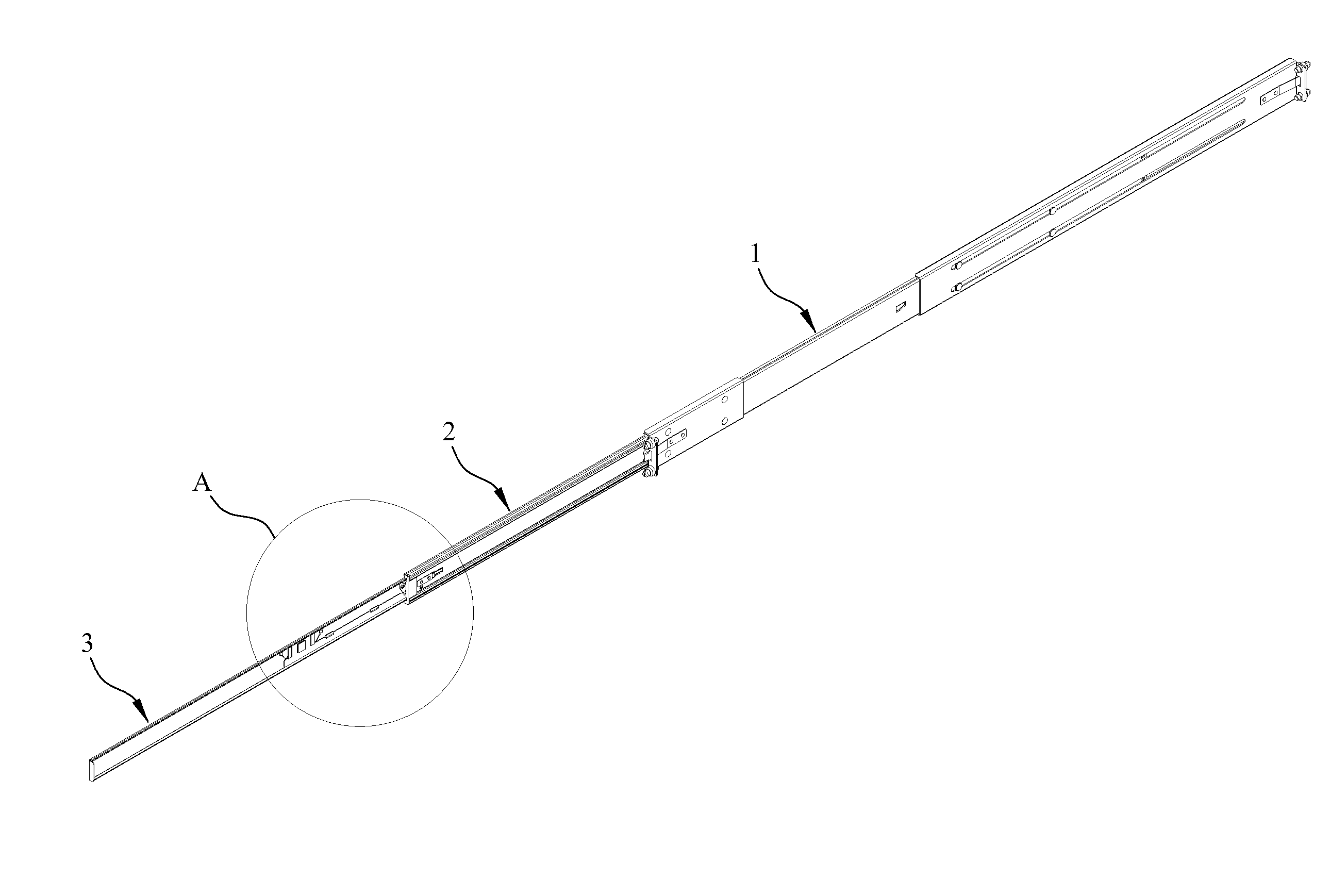
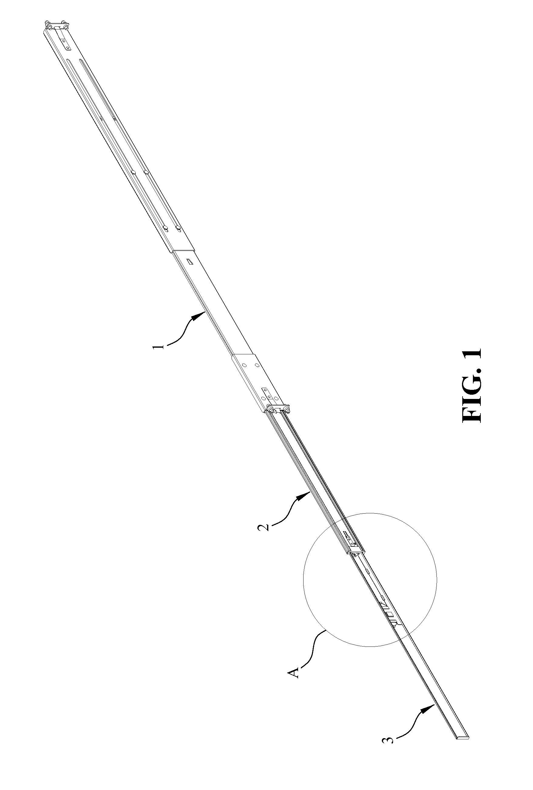
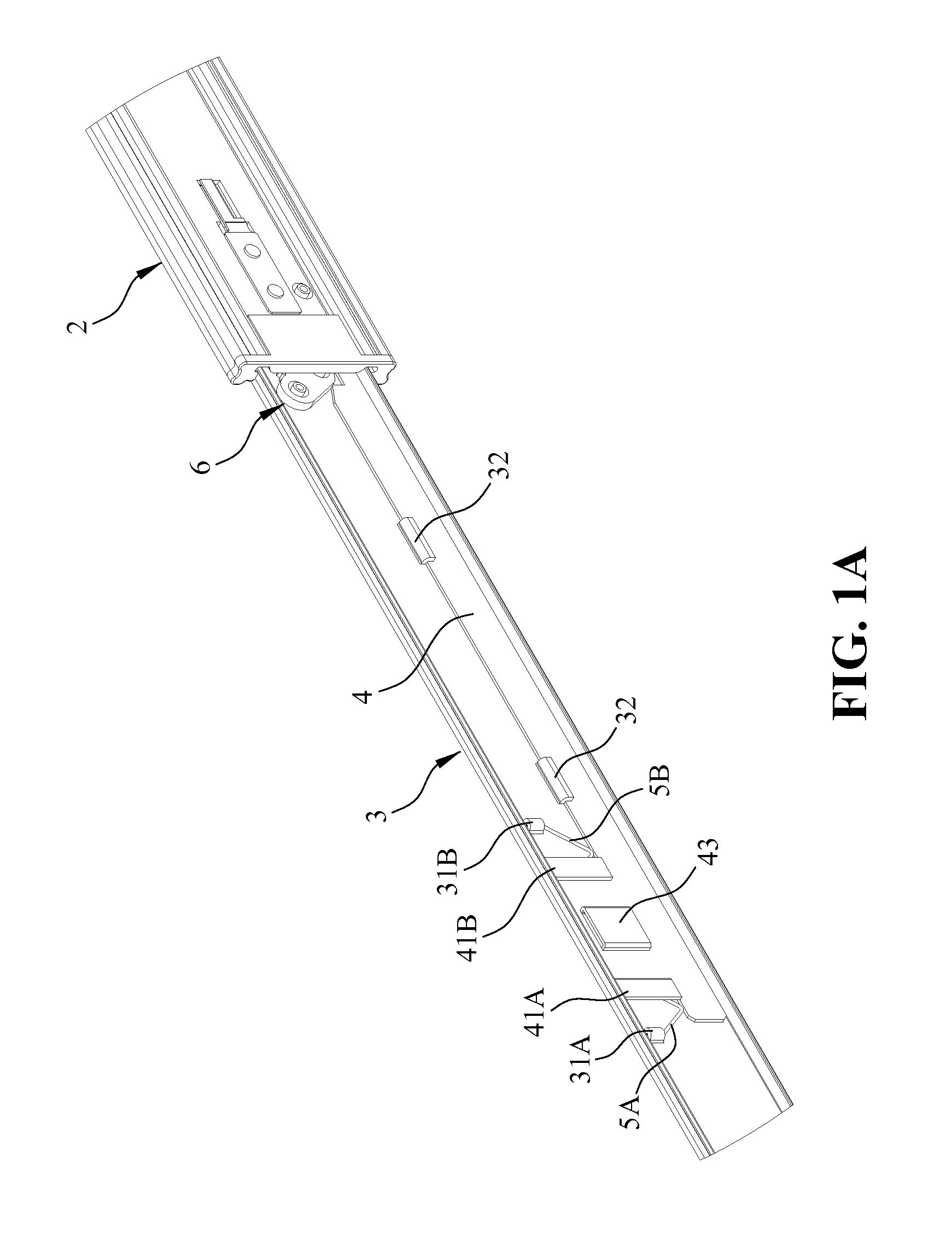
[0028]Referring to FIGS. 1 and 1A, wherein FIG. 1 is a perspective view of a slide positioning device of the present invention for use in a sliding mechanism; and FIG. 1A is an enlarged view of an encircled portion of FIG. 1. The slide positioning device of the present invention is used in an electronic device, such as for mounting a server in PC. The sliding mechanism includes an exterior plate 1, which is generally fixed to a side wall of the PC for receiving the server, an intermediate plate 2 connected slidably to the exterior plate 1 and an interior plate 3 connected slidably to the intermediate plate 2 and which generally holds the server thereon such that the server is dispose...


PUM


Abstract

A positioning device for a sliding mechanism that includes exterior, intermediate and interior plates, each plate defining inner and outer side surfaces, the positioning device is characterized by: the intermediate plate having a stop block formed on the inner side surface; and the interior plate including an elongated release rod that is mounted movably on the outer side surface and that has a limit notch receiving the block, and a resilient element engaging the propeller portion for restricting a longitudinal movement of the rod, the interior plate having a position limiting unit constituted by two limiting stubs mounted movably on the outer side surface and having pointed free ends and a biasing element for biasing the limiting stubs in such a manner that the pointed free ends extend into the notch to contact opposite ends of the block, thereby preventing relative movement between the interior and intermediate plates.

Description

BACKGROUND OF THE INVENTION[0001]1. Field of the Invention[0002]The present invention relates generally to a fixing device, and more particularly to a fixing device for a sliding mechanism consisting of slidably connected exterior, intermediate and interior plates, wherein once the interior plate is pulled outward from the intermediate plate, the interior plate is retained stably outside of the intermediate plate or the interior plate is easily removed from the intermediate plate if desired, thereby facilitating the user.[0003]2. The Prior Arts[0004]In a personal computer (PC), a server is mounted slidably to a computer casing via two slide plates, which cooperatively define a slide channel therebetween. In case of repairing, the server can be pulled outward from the casing and after the repairing the server is pushed slidably back into the casing. A conventional sliding mechanism used in a PC generally includes an exterior plate, an interior plate and sometimes an intermediate plat...

Claims


Application Information

Patent Timeline
IPC IPC(8): F16M13/02A47B88/00A47B88/04
CPCF16M13/022A47B88/0085A47B88/04A47B2210/0081A47B88/49H05K7/1489
Inventor HSU, KUO-MINGHUANG, TZU-CHIENLEE, HSIN-HANWU, YOU-LUN
Owner JOCHU TECH
Learn More