Slim fan structure

a fan structure and fan technology, applied in the direction of liquid fuel engines, instruments, machines/engines, etc., can solve the problems of reducing computing speed, affecting the performance of electronic elements, increasing heat produced by these chips during the operation of these engines, etc., to reduce the overall thickness, reduce noise, and improve the effect of operating performan

Active Publication Date: 2015-12-10
ASIA VITAL COMPONENTS SHENZHEN CO LTD
View PDF8 Cites 2 Cited by
  • Summary
  • Abstract
  • Description
  • Claims
  • Application Information

AI Technical Summary

Benefits of technology

[0007]To overcome the disadvantages of the conventional centrifugal fan, it is a primary object of the present invention to provide a slim fan structure that has effectively reduced overall thickness and upgraded operating performance.
[0008]Another object of the present invention is to provide a slim fan structure that enables effectively reduced noise during fan operation.
[0009]To achieve the above and other objects, the slim fan structure according to the present invention includes a top cover, a fan frame, a stator assembly and a hub. The top cover is closed onto a top of the fan frame, so that a receiving space is defined between the top cover and the fan frame. The fan frame includes a shaft holder located in the receiving space, and has a first side, a second side located adjacent to the first side, a third side located opposite to the first side, and a fourth side located opposite to the second side. The first side has an air inlet formed thereon and the third side has an air outlet formed thereon. The second side is formed with a first side wall, and the fourth side is formed with a second side wall. The first side wall includes a laterally protruded portion extended toward the air i

Problems solved by technology

However, with the constantly increased number and computing speed of chips inside the electronic elements, heat produced by these chips during operation thereof also increases.
The heat produced by the working chips must be timely removed from the electronic elements, lest it should adversely affect the performance of the electronic elements to result in lowered computing speed thereof.
Further, the electronic elements are subject to burnout when the heat accumulates without being timely removed from the elec

Method used


Image

  • Slim fan structure
  • Slim fan structure
  • Slim fan structure

Examples


Embodiment Construction

[0021]The present invention will now be described with some preferred embodiments thereof and with reference to the accompanying drawings. For the purpose of easy to understand, elements that are the same in the preferred embodiments are denoted by the same reference numerals.

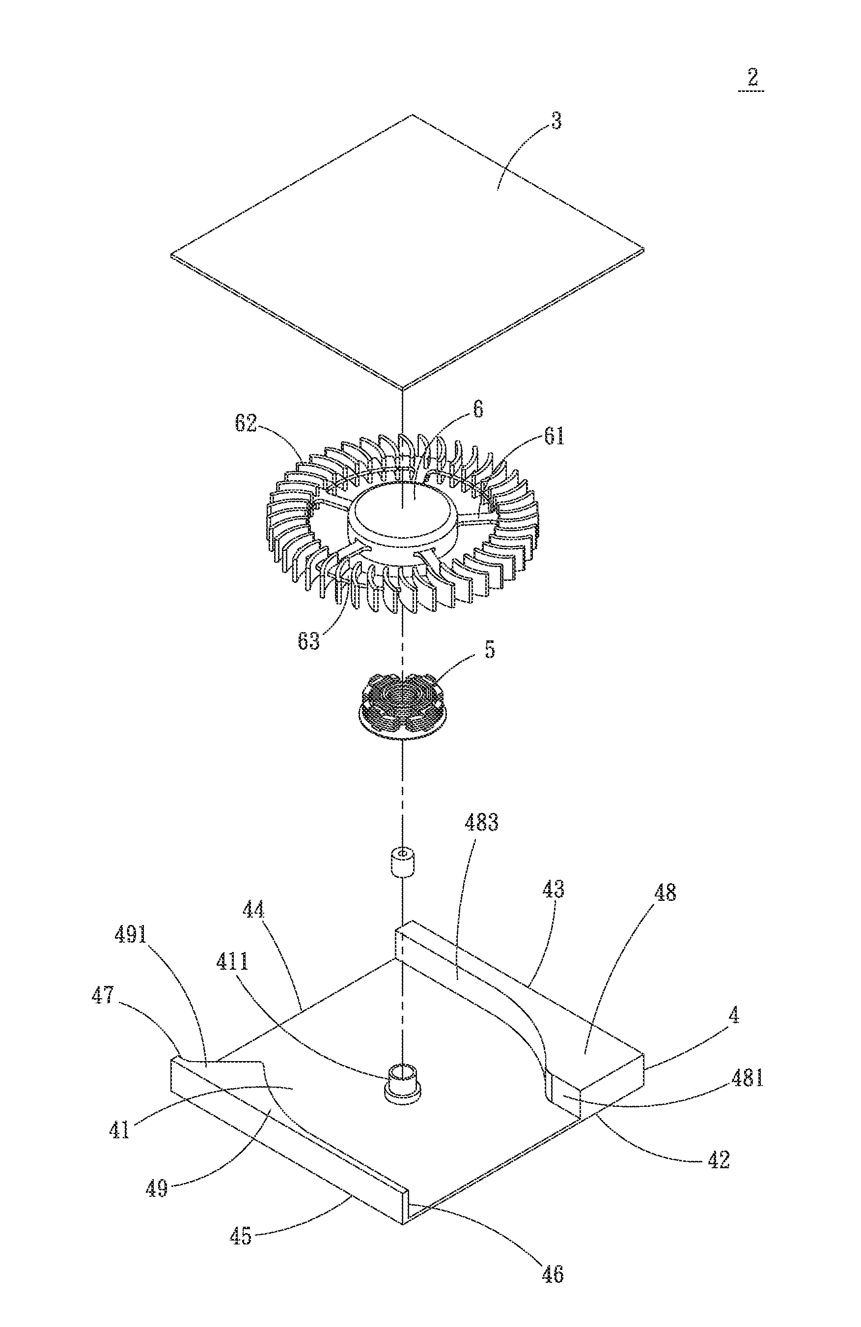
[0022]Please refer to FIGS. 2, 3 and 4, wherein FIG. 2 is an exploded perspective view showing a slim fan structure 2 according to a first preferred embodiment of the present invention, FIG. 3 is a partially assembled view of FIG. 2, and FIG. 4 is a plan view of the slim fan structure 2 of FIG. 3 with a top cover 3 removed therefrom. As shown, the slim fan structure 2 in the first preferred embodiment includes a top cover 3, a fan frame 4, a stator assembly 5, and a hub 6.

[0023]The top cover 3 is closed onto a top of the fan frame 4, so that a receiving space 41 is defined between the top cover 3 and the fan frame 4. The fan frame 4 includes a shaft holder 411 located in the receiving space 41 near a center the...


PUM


Abstract

A slim fan structure includes a fan frame, a top cover closed to a top of the fan frame to define a receiving space in the fan frame, a stator assembly mounted in the receiving space, and a hub fitted around the stator assembly. The fan frame has opposite first and third sides forming an air inlet and an air outlet, respectively, and opposite second and fourth sides having a first and a second side wall formed thereon, respectively. The first side wall includes a protruded portion laterally extended toward the air inlet, and the second side wall includes a stop portion located adjacent to the air outlet. With the air inlet and the air outlet formed on two lateral sides of the fan frame, the slim fan structure has an effectively reduced overall thickness and does not produce noise during operation to largely upgrade the operational performance thereof.

Description

FIELD OF THE INVENTION[0001]The present invention relates to a fan structure, and more particularly to a slime fan structure that has a reduced overall thickness and produces less noise during operation to largely upgrade the fan's operational performance.BACKGROUND OF THE INVENTION[0002]Thanks to the rapid development of the electronic industry, the currently available electronic products now have electronic elements with largely upgraded performance and increased computing speed. However, with the constantly increased number and computing speed of chips inside the electronic elements, heat produced by these chips during operation thereof also increases. The heat produced by the working chips must be timely removed from the electronic elements, lest it should adversely affect the performance of the electronic elements to result in lowered computing speed thereof. Further, the electronic elements are subject to burnout when the heat accumulates without being timely removed from the ...

Claims


Application Information

Patent Timeline
IPC IPC(8): F04D29/40F04D19/00H05K7/20
CPCF04D29/403F04D19/002H05K7/20172F04D17/04F04D25/0613G06F1/203
Inventor WU, CHUN-MING
Owner ASIA VITAL COMPONENTS SHENZHEN CO LTD
Why Eureka
Try Eureka