
Engine starting apparatus with inrush current reducer

a technology of inrush current reducer and engine, which is applied in the direction of engine starters, electric motor starters, machines/engines, etc., can solve the problems of large increase in current flowing through the electric motor, great drop in terminal voltage, and inability to operate solenoid actuators, etc., to achieve the effect of reducing current value, maximizing engine friction, and high torqu

Inactive Publication Date: 2015-12-10
DENSO CORP
View PDF32 Cites 7 Cited by
  • Summary
  • Abstract
  • Description
  • Claims
  • Application Information

AI Technical Summary

Benefits of technology

The patent describes a way to start an engine more quickly and with less electrical current when the engine is hot from being stopped. This is achieved by using a special mode to rotate the starter at a low speed to produce high torque at the moment the piston reaches its highest point in the engine. This reduces the amount of electric power needed and improves fuel economy in the vehicle.

Problems solved by technology

Usually, too large an inrush current flowing through an electric motor of an engine starter when starting an engine will result in a great drop in terminal voltage at a storage battery, which may cause electronic control units (ECUs) installed in a vehicle to be reset or operations of solenoid actuators to be unstable.
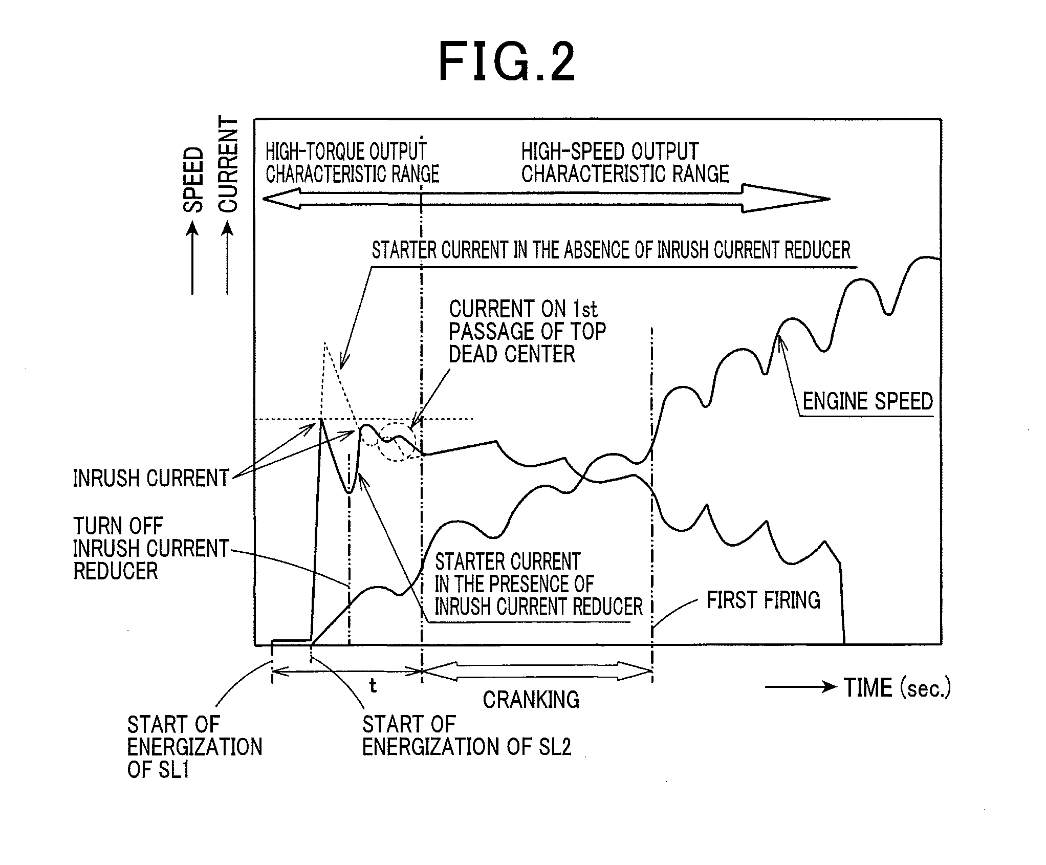
However, when the engine starter is placed in the high-speed mode to start the engine, the torque, as outputted by the engine starter, is usually low, thus resulting in a great increase in current flowing through the electric motor when the piston of the engine passes the top dead center for the first time.
This current, as illustrated in FIG. 3, may exceed the value of inrush current, as decreased by the ICR relay, thus encountering the drawback in that the level of the inrush current is not kept below a permissible level.
However, when a low-torque / high-speed type starter is used to shorten a period of time required to start up the engine, too low a degree of torque may cause a value of current flowing through the electric motor of the starter to be higher when the piston passes the top dead center than a value of the inrush current decreased by the inrush current reducer.
The maximum effects expected to be offered by the inrush current reducer will not, therefore, be obtained, which results in a risk that some defects arise from a drop in voltage at the battery such as the resetting of ECUs or instability in operation of solenoids installed in the vehicle.
This results in a decrease in value of current flowing through the electric motor of the starter at the moment when the engine friction is maximized.

Method used


Image

  • Engine starting apparatus with inrush current reducer
  • Engine starting apparatus with inrush current reducer
  • Engine starting apparatus with inrush current reducer

Examples


Embodiment Construction

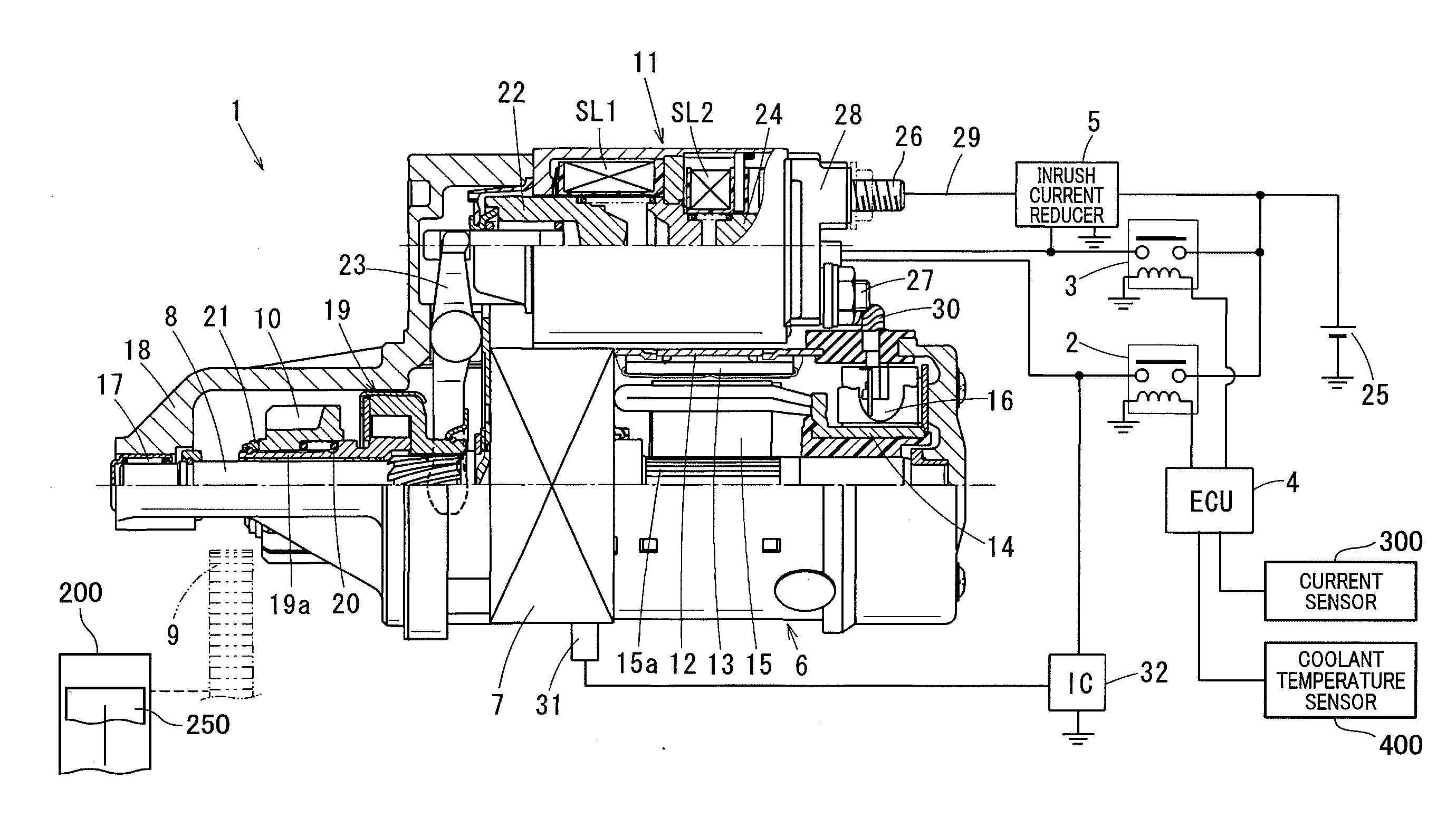
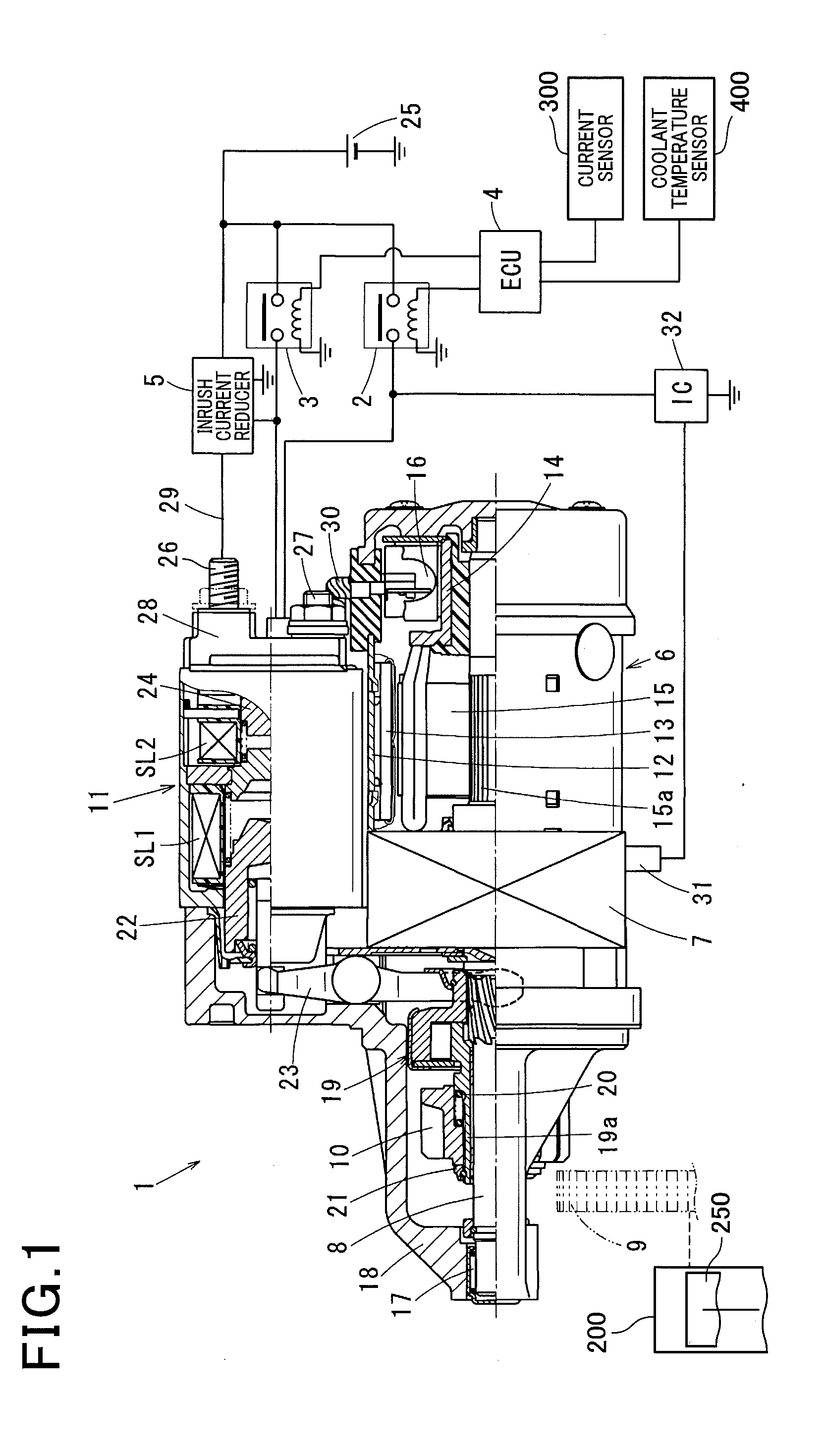
[0020]Referring to the drawings, wherein like reference numbers refer to like parts in several views, particularly to FIG. 1, there is shown an engine starting apparatus according to an embodiment. The engine starting apparatus includes an engine starter 1, a controller 4, an inrush current reducer 5, and a starter characteristic selector (which will also be described below in detail). The controller 4 is implemented by an electronic control unit (ECU) and works to control an operation of the engine starter 1 through starter relays 2 and 3. The inrush current reducer 5 is installed in a starting circuit of the starter 1. The starter characteristic selector is engineered to change output characteristics of the starter 1 (which will also be referred to as starter characteristics below) continuously or at least between two modes.

[0021]The starter 1 is made up of an electric motor 6, an output shaft 8, a pinion 10, and an electromagnetic solenoid device 11 which will be described later ...


PUM


Abstract

An engine starting apparatus is provided which is equipped with a starter, an inrush current reducer, and a starter mode switch. The inrush current reducer works to reduce an inrush current flowing through an electric motor installed in the starter when the electric motor is energized. The starter mode switch works to change a starter characteristic that is an output characteristic of the starter continuously or selectively at least between a low-torque / high-speed mode and a high-torque / low-speed mode. The starter mode switch places the starter in the high-torque / low-speed mode at least at a time when a piston of the engine is passing a top dead center, and the engine friction has been just maximized for the first time after the starter is actuated to crank the engine. This shortens a period of time required to start up the engine without sacrificing beneficial effects offered by the inrush current reducer.

Description

CROSS REFERENCE TO RELATED DOCUMENT[0001]The present application claims the benefit of priority of Japanese Patent Application No. 2014-115602 filed on Jun. 4, 2014, the disclosure of which is incorporated herein by reference.BACKGROUND OF THE INVENTION[0002]1 Technical Field[0003]This disclosure relates generally to an engine starting apparatus which is equipped with an inrush current reducer to reduce an inrush current drawn by an electric motor when energized.[0004]2 Background Art[0005]Usually, too large an inrush current flowing through an electric motor of an engine starter when starting an engine will result in a great drop in terminal voltage at a storage battery, which may cause electronic control units (ECUs) installed in a vehicle to be reset or operations of solenoid actuators to be unstable. In order to reduce the inrush current flowing through the electric motor, Japanese Patent First Publication No. 2009-224315 teaches installing an ICR (Inrush Current Reduction) rela...

Claims


Application Information

Patent Timeline
IPC IPC(8): F02N11/08
CPCF02N11/087F02N11/0851F02N15/023F02N15/046F02N15/067F02N2015/061F02N2200/023F02N2200/044F02N2300/102F02N2300/104F02N2300/2011
Inventor HIRABAYASHI, TAKASHI
Owner DENSO CORP
Learn More