
Identification and rejection of asymmetric faults

a technology of asymmetric faults and faults, applied in the direction of electrical control, process and machine control, instruments, etc., can solve the problems bias of uego sensor reading rich or lean of stoichiometry, and significant feedgas emissions, so as to maintain drivability and noise, vibration, and harshness (nvh) constraints, the effect of increasing the risk of generating significant tailpipe emissions

Active Publication Date: 2015-12-10
FORD GLOBAL TECH LLC
View PDF25 Cites 8 Cited by
  • Summary
  • Abstract
  • Description
  • Claims
  • Application Information

AI Technical Summary

Benefits of technology

The patent text describes a system and method for identifying and rejecting asymmetric faults that cause engine emissions to be biased rich or lean. This is achieved by monitoring the feedback from two exhaust gas sensors and adjusting the air-fuel ratio to a set point based on the deviation of the sensors. The system can also disable monitoring the reference air-fuel ratio for a pre-determined amount of time responsive to a deceleration fuel shutoff event. The technical effect of this patent is to improve the accuracy of engine emissions control and prevent excessive emissions in the presence of asymmetric faults.

Problems solved by technology

However, various faults, such as AFR imbalance between cylinders, could bias the UEGO sensor reading rich or lean of stoichiometry.
This can lead to significant feedgas emissions such as carbon monoxide (CO) or the oxides of nitrogen (NOx) passing directly to the tailpipe, as the biased air / fuel mixture is fed directly to the catalyst, overwhelming the oxygen-storage buffer that allows for short deviations from stoichiometry.
These asymmetric faults may be caused, for example, by a degraded UEGO sensor, cylinder imbalance resulting from a degraded fuel injector, or an error incurred during a deceleration fuel shutoff event.
Detecting and correcting for asymmetric biasing may include first running an intrusive diagnostics test, thereby increasing the risk of generating significant tailpipe emissions in the presence of an existing biasing fault.

Method used


Image

  • Identification and rejection of asymmetric faults
  • Identification and rejection of asymmetric faults
  • Identification and rejection of asymmetric faults

Examples


Embodiment Construction

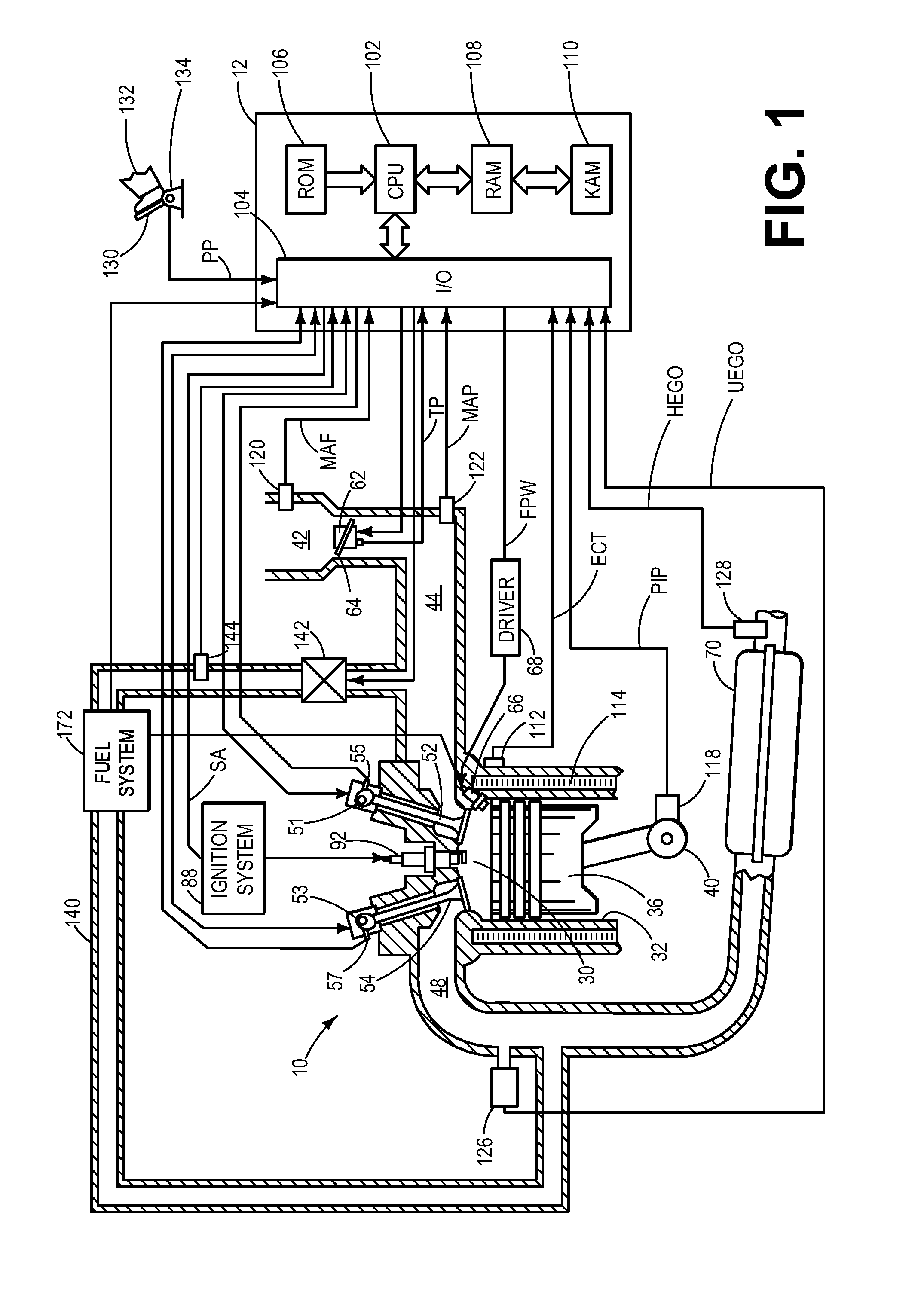
[0016]The following description relates to systems and methods for identifying and rejecting asymmetric faults in an exhaust after-treatment system of a vehicle. As shown in FIG. 1, the vehicle may be configured with a three-way catalyst for exhaust after-treatment in addition to exhaust gas oxygen sensors upstream and downstream of the catalyst. These exhaust gas oxygen sensors may comprise a catalyst control architecture including inner and outer control loops, such as the one shown in FIG. 2. A generic mid-ranging control architecture is shown in FIG. 3A and is modified for outer loop control, as shown in FIG. 3B. In the modified approach, the control action of the outer loop is monitored over time in order to identify and reject asymmetric faults. Following a deceleration fuel shutoff event, the catalyst is necessarily biased rich to regenerate the catalyst from a saturated oxygen state. This process of catalyst regeneration will interfere with appropriately monitoring the outer...


PUM


Abstract

Methods and systems are provided for identifying and rejecting asymmetric faults that cause engine emissions to be biased rich or lean. In one example, a method for an engine system comprises generating a UEGO sensor feedback set-point adjustment based on slower and faster time components within an outer loop of a catalyst control system; generating an inner-loop bias-offset correction from the slower time component; and indicating degradation of the engine system based on a comparison of the bias-offset correction to a degradation threshold. In this way, the total outer-loop control authority is increased while maintaining drivability and noise, vibration, and harshness (NVH) constraints and meeting emission standards in the presence of an air-to-fuel ratio biasing fault.

Description

BACKGROUND AND SUMMARY[0001]Modern vehicles use three-way catalysts (TWC) for exhaust after-treatment of gasoline engines. With tightening government regulations on automobile emissions, feedback control is used to adequately regulate the engine air-to-fuel ratio (AFR). Some vehicles have a universal exhaust gas oxygen (UEGO) sensor upstream of the TWC and a heated exhaust gas oxygen (HEGO) sensor downstream of the TWC to control the AFR near stoichiometry. This is achieved by regulating the AFR to a set point around stoichiometry, which in turn is fine-tuned based on the deviation of a HEGO voltage from a pre-determined HEGO-voltage set-point.[0002]However, various faults, such as AFR imbalance between cylinders, could bias the UEGO sensor reading rich or lean of stoichiometry. This can lead to significant feedgas emissions such as carbon monoxide (CO) or the oxides of nitrogen (NOx) passing directly to the tailpipe, as the biased air / fuel mixture is fed directly to the catalyst, o...

Claims


Application Information

Patent Timeline
Patent Type & Authority Applications(United States)
IPC IPC(8): F02D41/04F02D41/22
CPCF02D41/22F02D41/04F02D41/1441F02D41/1454F02D41/1456F02D41/1495F02D2041/1409F02D2041/1419F02D2041/1431F02D2041/1432
Inventor SANTILLO, MARIO ANTHONYMAGNER, STEPHEN WILLIAMUHRICH, MICHAEL JAMESJANKOVIC, MRDJAN J.
Owner FORD GLOBAL TECH LLC
Learn More