
Aircraft systems and methods with integrated tank inerting and power generation

Inactive Publication Date: 2015-12-10
HONEYWELL INT INC
View PDF3 Cites 18 Cited by
  • Summary
  • Abstract
  • Description
  • Claims
  • Application Information

AI Technical Summary

Benefits of technology

This patent describes a system for inerting a fuel tank of an aircraft by using a compressor to remove air and vapor from the tank. The system also includes a fuel processor to generate hydrogen from the air and vapor, a fuel cell to use the hydrogen to produce electricity, and a combustor to combust the exhaust product produced by the fuel cell and produce inerting gas for the tank. The technical effect is the generation of a safer and more efficient inerting gas for the fuel tank of an aircraft.

Problems solved by technology

Because these inerting techniques are performed in-flight, energy that would otherwise be available to power the aircraft may need to be used to inert the fuel tank, thus negatively impacting overall efficiency.
Moreover, conventional inerting equipment also adds weight to an aircraft, which further impacts efficiency.

Method used


Image

  • Aircraft systems and methods with integrated tank inerting and power generation
  • Aircraft systems and methods with integrated tank inerting and power generation
  • Aircraft systems and methods with integrated tank inerting and power generation

Examples


Embodiment Construction

[0013]The following detailed description is merely exemplary in nature and is not intended to limit the invention or the application and uses of the invention. As used herein, the word “exemplary” means “serving as an example, instance, or illustration.” Thus, any embodiment described herein as “exemplary” is not necessarily to be construed as preferred or advantageous over other embodiments. All of the embodiments described herein are exemplary embodiments provided to enable persons skilled in the art to make or use the invention and not to limit the scope of the invention which is defined by the claims. Furthermore, there is no intention to be bound by any expressed or implied theory presented in the preceding technical field, background, brief summary, or the following detailed description.

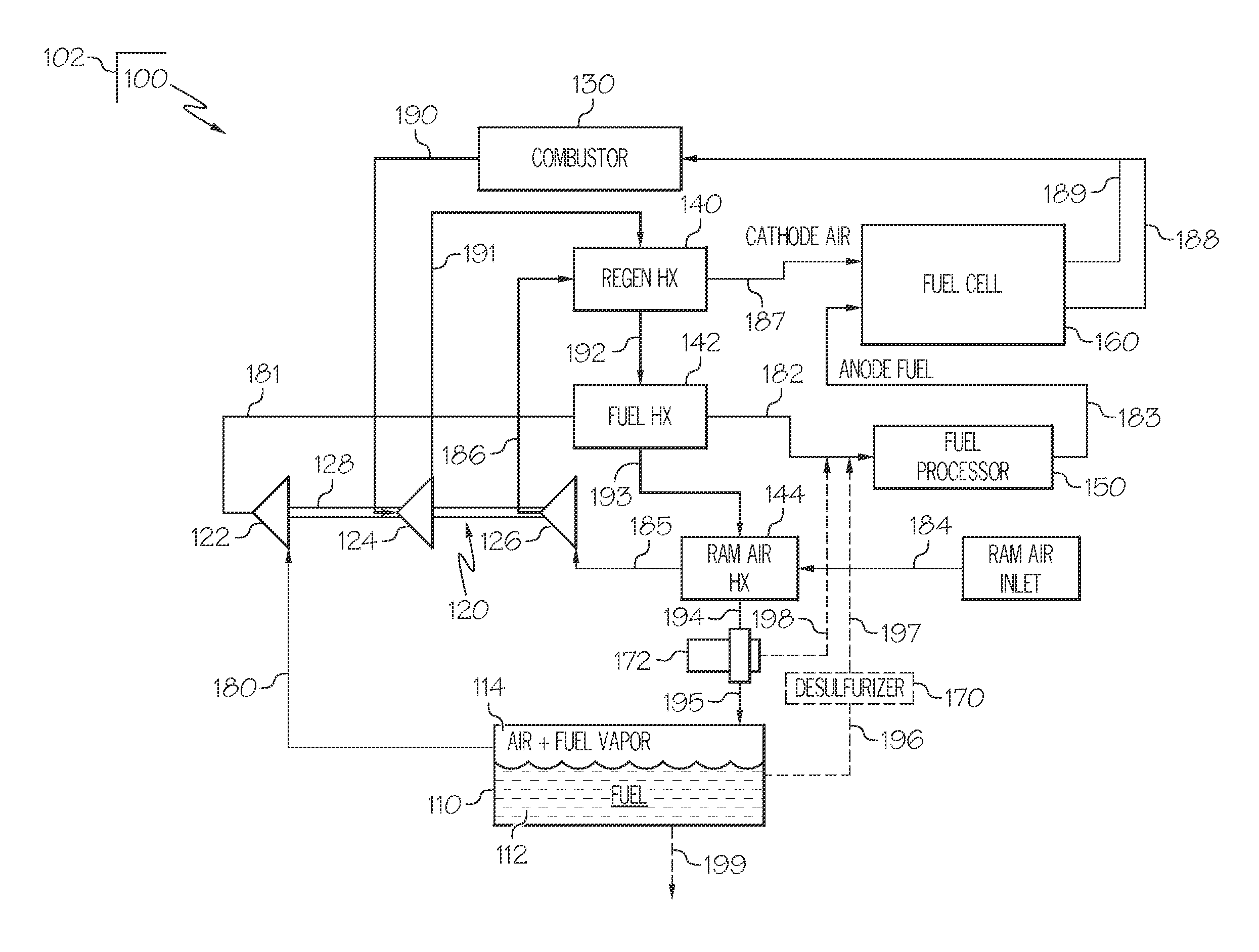
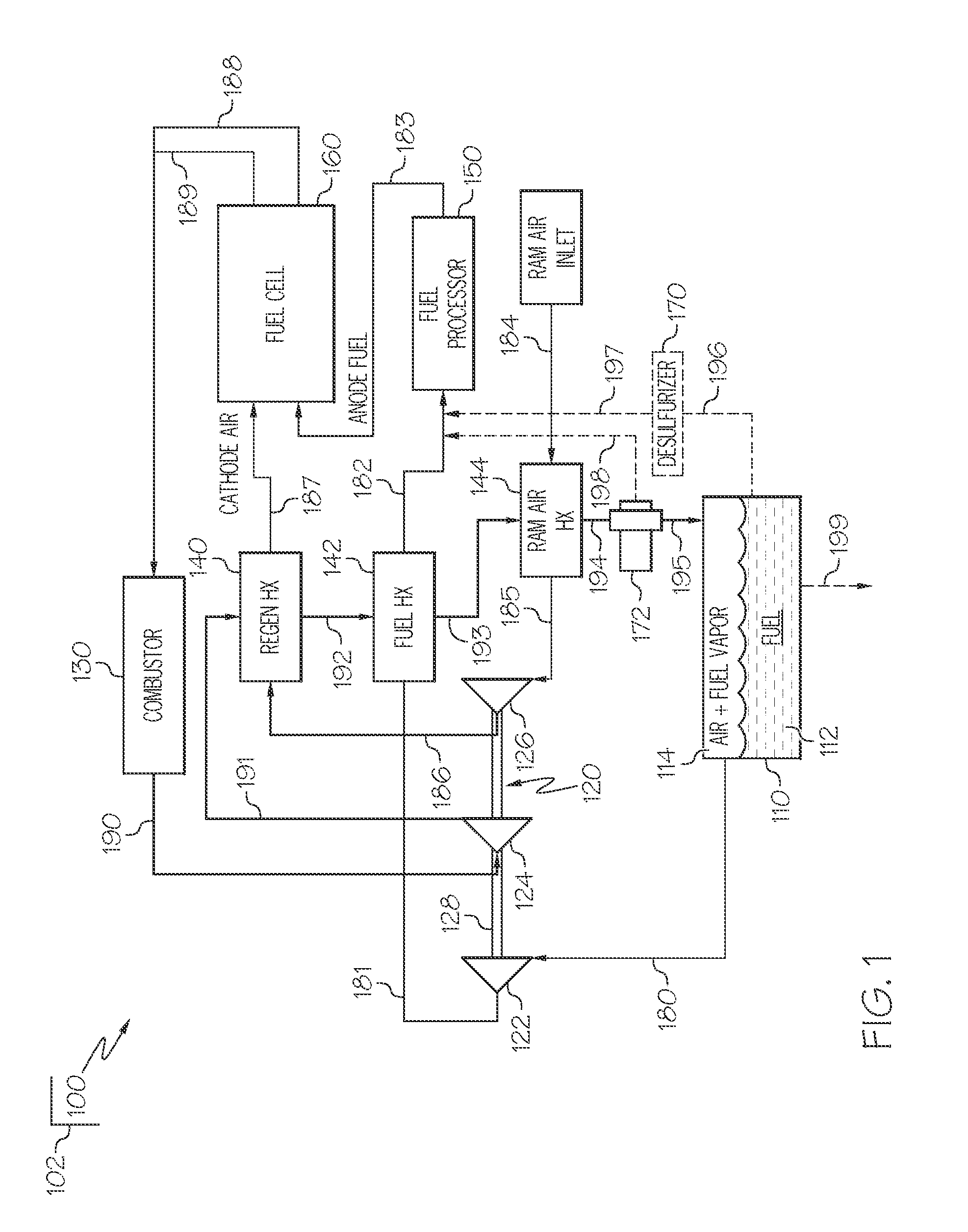
[0014]FIG. 1 is a schematic block diagram of an aircraft system 100 for integrated fuel tank inerting and power generation in accordance with an exemplary embodiment. The system 100 may be hous...


PUM


Abstract

A system is provided for inerting a fuel tank of an aircraft. The system includes a first compressor fluidly coupled to the fuel tank for removing an air and fuel vapor mixture from an ullage of the fuel tank. The system further includes a fuel processor fluidly coupled to the first compressor and configured to receive the air and fuel vapor mixture and to generate hydrogen from the air and fuel vapor mixture. The system further includes a fuel cell fluidly coupled to the fuel processor and configured to receive the hydrogen as anode fuel to produce electricity. The system further includes a combustor fluidly coupled to the fuel cell and configured to combust the exhaust product to produce combustion gas, and a first heat exchanger fluidly coupled to the combustor and configured to cool the combustion gas into inerting gas for the fuel tank.

Description

TECHNICAL FIELD[0001]The present invention generally relates to aircraft systems and methods, and more particularly relates to aircraft systems and methods for inerting a fuel tank.BACKGROUND[0002]Aircraft fuel tanks generally include a fuel portion containing liquid fuel and an ullage portion containing a mixture of air and fuel vapor. The ullage portion should be inerted to prevent or mitigate the possibility of igniting the air and fuel vapor mixture. Various inerting technologies have been employed to alter the chemical composition of the mixture. In particular, inerting may be achieved by either reducing the oxygen concentration to less than 12% by volume and / or reducing the fuel to air ratio to less than 0.03 by weight. As examples, such inerting techniques may include in-flight purging of fuel vapor from tanks and condensing the purged vapor to reduce the fuel to air ratio, or in-flight generation of inerting gas such as nitrogen or CO2 and injection of the inert gas into the...

Claims


Application Information

Patent Timeline
IPC IPC(8): B64D37/32A62C3/06A62C3/08
CPCB64D37/32A62C3/065A62C3/08B64D2041/005H01M8/04014H01M8/04111H01M8/0618Y02E60/50Y02T90/40B64D41/00F02C3/04F02C6/00F02C7/22F05D2220/50F05D2220/76F05D2240/35H01M2250/20
Inventor HAGH, BIJAN F.ZHENG, DAGUANGJOHNSON, RUSSELL W.ACHARYA, MUKUNDSCAINI, MARIO
Owner HONEYWELL INT INC
Learn More