
Solar photovoltaic module power control and status monitoring system utilizing laminate-embedded remote access module switch

a solar photovoltaic module and power control technology, applied in photovoltaic supports, pv power plants, sustainable buildings, etc., can solve the problems of increasing the cost and complexity of pv modules, difficult to control the electrical power output of modules, and complex fabrication, so as to improve module safety and anti-theft, reduce the impact of module power generation, and reduce the effect of insertion losses

Inactive Publication Date: 2015-12-03
BEAMREACH SOLAR INC +1
View PDF0 Cites 25 Cited by
  • Summary
  • Abstract
  • Description
  • Claims
  • Application Information

AI Technical Summary

Benefits of technology

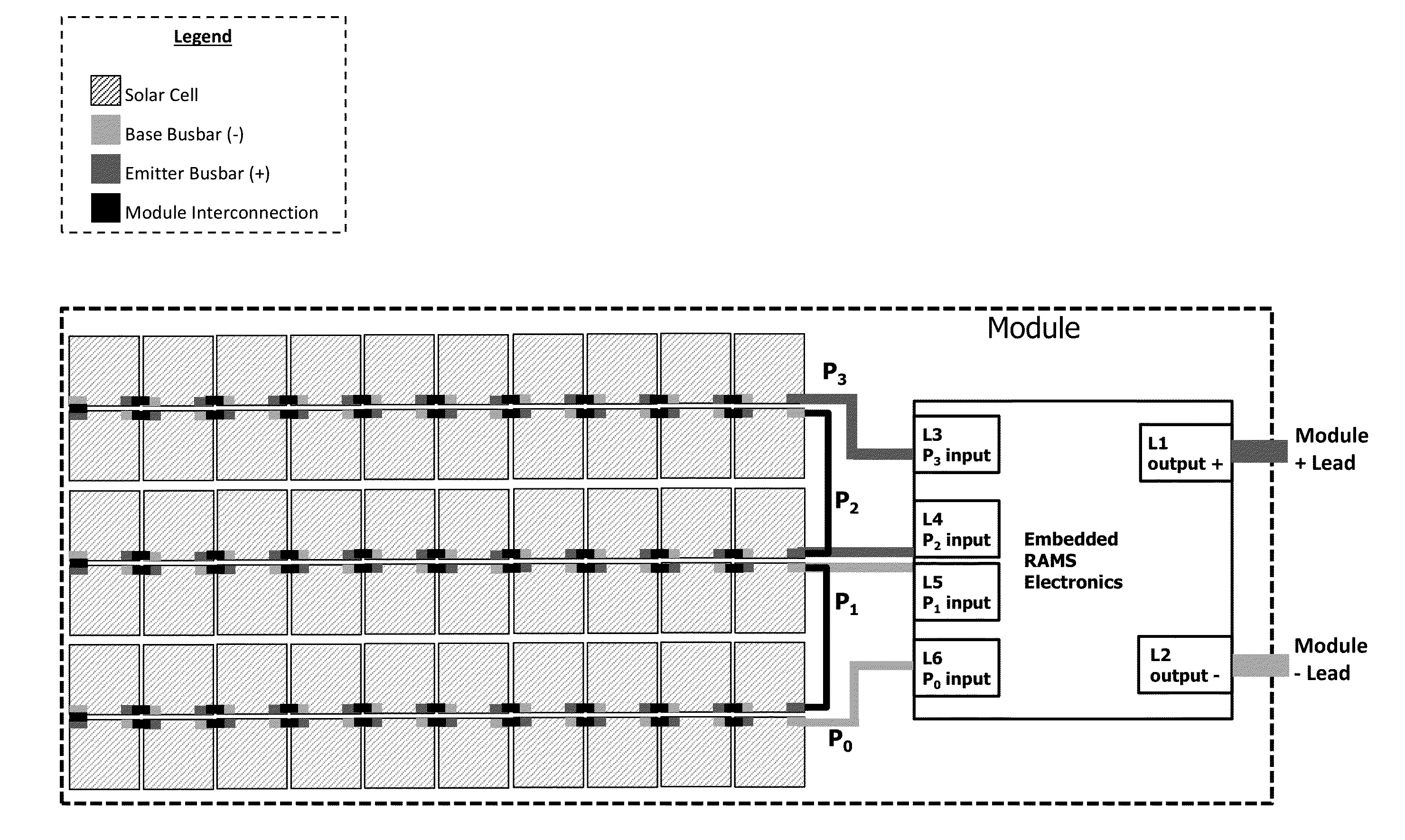
[0006]Therefore, a need has arisen for simple-to-implement and secure module power control and status monitoring systems that provide increased module safety and anti-theft improvements with minimal module power generation impact (i.e., minimal insertion losses). In accordance with the disclosed subject matter, a module power control (and status monitoring) system utilizing a remote access control switch (RAMS) is provided which substantially eliminates or reduces disadvantages associated with previously developed module power control systems.

Problems solved by technology

Further, it is often difficult to control the electrical power output of the module and existing control systems rely on external electrical breaker switches or other module external means to connect or disconnect module outputs.
These solutions are often discrete external module level components which leave hot module wires, are prone to failure, and require complex fabrication.
The external micro-inverter or DC-DC power optimizers can disconnect the module power delivery to the load but they add significant cost and complexity to the PV modules and do not disconnect the module power delivery internally within the module laminate.

Method used


Image

  • Solar photovoltaic module power control and status monitoring system utilizing laminate-embedded remote access module switch
  • Solar photovoltaic module power control and status monitoring system utilizing laminate-embedded remote access module switch
  • Solar photovoltaic module power control and status monitoring system utilizing laminate-embedded remote access module switch

Examples


Embodiment Construction

[0021]The following description is not to be taken in a limiting sense, but is made for the purpose of describing the general principles of the present disclosure. The scope of the present disclosure should be determined with reference to the claims. Exemplary embodiments of the present disclosure are illustrated in the drawings, like numbers being used to refer to like and corresponding parts of the various drawings.

[0022]And although the present disclosure is described with reference to specific embodiments and components, such as a remote access module switch (RAMS) power electronic circuit controlled by a command signal, one skilled in the art could apply the principles discussed herein to other components and circuitry (such as a control switch with embedded memory or wireless control), technical areas, and / or embodiments without undue experimentation.

[0023]The present application provides a solution for effectively and efficiently controlling solar module power output while in...


PUM


Abstract

A solar photovoltaic module laminate for electric power generation is provided. The module comprises a plurality of solar cells embedded within the module laminate and electrically interconnected to form at least one string of electrically interconnected solar cells within said module laminate. And at least one remote-access module switch (RAMS) power electronic circuit embedded within the module laminate electrically interconnected to and powered with said at least one string of electrically interconnected solar cells and serving as a remote-controlled module power delivery gate switch.

Description

CROSS-REFERENCE TO RELATED APPLICATIONS[0001]This application claims the benefit of U.S. provisional patent applications 61 / 811,736 filed on Apr. 13, 2013 and 61 / 895326 filed on Oct. 24, 2013 which are all hereby incorporated by reference in their entirety.FIELD OF THE INVENTION[0002]The present disclosure relates in general to the fields of solar photovoltaic (PV) cells and modules, and more particularly power control and status monitoring systems for solar photovoltaic modules.BACKGROUND[0003]Advances in solar photovoltaics (PV) and solar cell technology have paved the path for cost-reduced mass production and large scale adoption of solar cells and modules as renewable clean energy production mechanisms. As this technology is implemented, there is an increased need for safety and power efficiency improvement at the cell, module, and system levels. A typical solar system comprises solar cells mounted and connected in a solar module laminate and a various assortment of string and s...

Claims


Application Information

Patent Timeline
Patent Type & Authority Applications(United States)
IPC IPC(8): H02S40/32H01L31/048H01L31/05H02S40/30
CPCH02S40/32H01L31/0504H01L31/048H02S40/30H01L31/02021H01L31/022441H01L27/1421H01L31/0516H01L31/1896H01L31/044Y02B10/10H02J2300/26H02J3/381Y02E10/548Y02E10/56H02S20/26H02S40/34
Inventor MOSLEHI, MEHRDAD M.
Owner BEAMREACH SOLAR INC
Learn More