
Systems, methods, and devices for fluid data sensing

Active Publication Date: 2015-12-03
UNIVERSITY OF KANSAS
View PDF5 Cites 3 Cited by
  • Summary
  • Abstract
  • Description
  • Claims
  • Application Information

AI Technical Summary

Benefits of technology

The present patent is about devices, systems, and methods for sensing data in flowing fluids, particularly at high or low fluid flow velocities and at high or low angulation. The device includes an outer body, an inner body, and an aft body with sensors, which induces the Coanda effect in the fluid by allowing it to flow into the hollow interior of the inner body. The device is useful for monitoring the status and performance of machines in environments that include fluid flow, such as aircraft. The technical effect of this patent is to provide accurate readings for fluid flow velocity and other fluid parameters.

Problems solved by technology

The accuracy of these measurements, however, may be limited at high / low fluid flow velocities and / or in conditions when the flow is not parallel to the measuring device.
For example, in aircraft or marine craft applications, measurement accuracy may suffer when the craft is changing direction or otherwise inducing pitch and / or yaw angles, such as during intense maneuvering or in loss of control situations, which are often among the situations where reliable data is typically most needed.
The requirement of multiple sensors and the necessity of gathering and interpreting separate signals into a meaningful measurement undesirably adds to the cost and complexity of fluid sensing, particularly in dynamic fluid flow environments.
In addition, typical devices used for measuring fluid flow parameters are configured to measure a single parameter only and / or are unable to provide accurate readings at high / low fluid flow velocities and / or indirect flow angles.
Typical systems intended to measure more than one fluid parameter may thus require multiple sensors, and the use of multiple sensors may result in readings that are not common to a localized area and / or that are not simultaneous, limiting the usefulness of the resulting readings for measuring certain fluid parameters.
Furthermore, inaccuracy of typical devices used for measuring angular fluid flow parameters propagates into estimation of local wind velocity and causes overestimation or underestimation of the wind speed.

Method used


Image

  • Systems, methods, and devices for fluid data sensing
  • Systems, methods, and devices for fluid data sensing
  • Systems, methods, and devices for fluid data sensing

Examples


example 1

[0064]A fluid sensing device according to the present disclosure was installed in parallel with a conventional Pitot tube in a wind tunnel measuring approximately 3 feet high, 4 feet wide, and 6 feet long. The fluid sensing device and the Pitot tube were installed on a tuntable that was turned in increments of 5 degrees with respect to the flow direction in the test section. The fluid sensing device included an inner body having an ellipsoid of revolution contour and an L / D ratio of 1.0. The ratio of the outer diameter of the outer body to the diameter of the inner body was 2.0. The outer body included a contoured lip with an elliptic shape having a semi-major to minor axis equal to 2. The fluid sensing device was calibrated to correct for inner body drag. Comparison tests were conducted at wind speeds of 27.5 m / s, 30.5 m / s, and 35 m / s, and the results are shown in FIGS. 9, 10, and 11, respectively.


PUM


Abstract

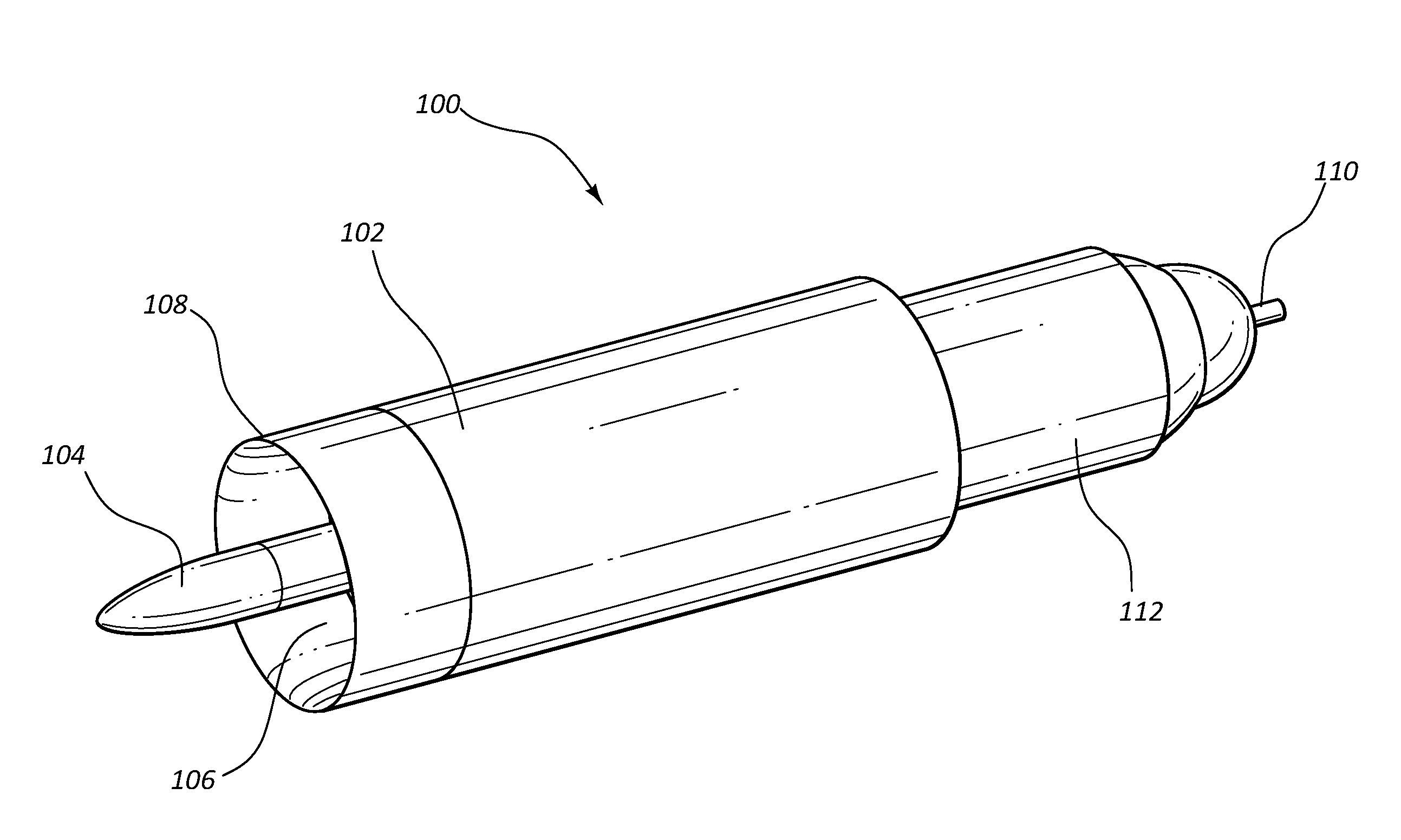
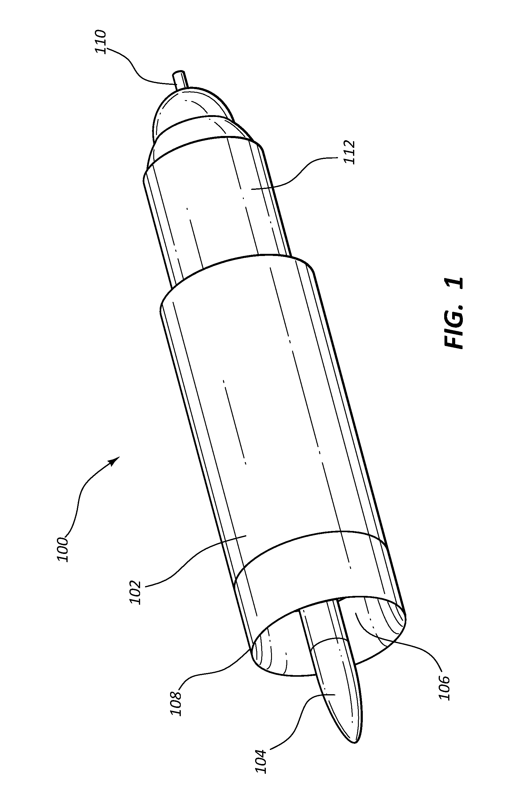
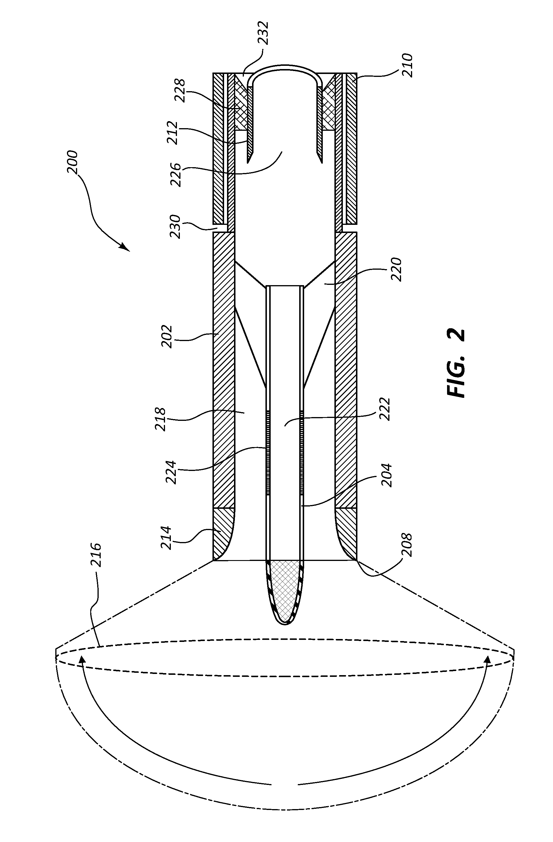
A fluid sensing device includes an outer body, an inner body coupled to the outer body by one or more inner body support struts and extending at least partially out from the outer body, and an aft body disposed at least partially within the outer body at a location aft of the inner body, the aft body being coupled to the outer body by one or more aft body support struts. The inner body includes a hollow interior for housing one or more inner body sensors, and the aft body houses one or more aft body sensors. The fluid sensing device can measure one or more parameters of fluid flow at high angularity, such as total temperature and total pressure, locally and simultaneously, allowing additional fluid parameters, such as local entropy, to be calculated.

Description

CROSS-REFERENCE TO RELATED APPLICATIONS[0001]This application is a non-provisional application claiming priority under 35 U.S.C. §119(e) to U.S. patent application Ser. No. 62 / 006,437, filed on Jun. 2, 2014 and titled “SYSTEMS, METHODS, AND APPARATUSES FOR DATA SENSING,” and to U.S. patent application Ser. No. 62 / 100,822, filed on Jan. 7, 2015 and titled “SYSTEMS, METHODS, AND APPARATUSES FOR DATA SENSING,” which applications are expressly incorporated herein in their entirety by this reference.BACKGROUND[0002]The present disclosure relates generally to sensing one or more fluid parameters. More specifically, the present disclosure relates to systems, devices, and methods for accurately measuring fluid flow velocity and / or other fluid parameters at high / low velocities and / or at indirect angular flows relative to a measurement probe.[0003]Fluid flow velocity measurements are typically determined by measuring pressure using some variation of a Pitot tube. The accuracy of these measure...

Claims


Application Information

Patent Timeline
IPC IPC(8): G01F1/05
CPCG01F1/05G01F1/46G01K13/02G01K13/028G01P5/165G01K13/024G01L2019/0053G01L19/0092
Inventor FAROKHI, SAEEDTAGHAVI, RAY R.KESHMIRI, SHAWN S.
Owner UNIVERSITY OF KANSAS
Learn More