
Method for centrifugal casting of motor rotor

a technology of centrifugal casting and motor rotor, which is applied in the manufacture of cage rotors, stator/rotor bodies, etc., can solve the problems of non-dense structure, many pores, and severe shrinkage, so as to improve the fluidity of molten metal injection, prevent incomplete forming, and reduce temperature differences

Inactive Publication Date: 2015-12-03
HYUNDAI HEAVY IND CO LTD
View PDF1 Cites 7 Cited by
  • Summary
  • Abstract
  • Description
  • Claims
  • Application Information

AI Technical Summary

Benefits of technology

The present invention provides a method for centrifugal casting of a motor rotor, which involves assembling and heating the upper, lower, and core molds before injecting molten metal. This improves the flow of the metal and the quality of the final product, while also making the process safer and easier for operators. The technical effects of this invention include better rotor formation, improved fluidity of the molten metal, and reduced difference in temperature between the metal and molds, resulting in a higher quality product.

Problems solved by technology

Die-casting has problems such as many pores, severe shrinkage, and non-dense structure due to injection of molten metal at high speed to prevent coagulation of the molten metal.
However, the conventional centrifugal casting method has been restrictively applicable to only the small motor rotor since only the upper and lower molds are preheated and thus the molten metal has low fluidity within the molds due to difference in temperature between the molten metal and the core when the molten metal is injected into the molds in practice.
As a result, there is a problem of incomplete forming of the rotor.
Moreover, in the conventional centrifugal casting method, since the upper and lower molds are preheated by the torch and then assembled with the core, safety accident frequently occur in operation.

Method used


Image

  • Method for centrifugal casting of motor rotor
  • Method for centrifugal casting of motor rotor
  • Method for centrifugal casting of motor rotor

Examples


Embodiment Construction

[0029]Hereinafter, a method for centrifugal casting of a motor rotor in accordance with one embodiment of the present invention will be described with reference to the accompanying drawings.

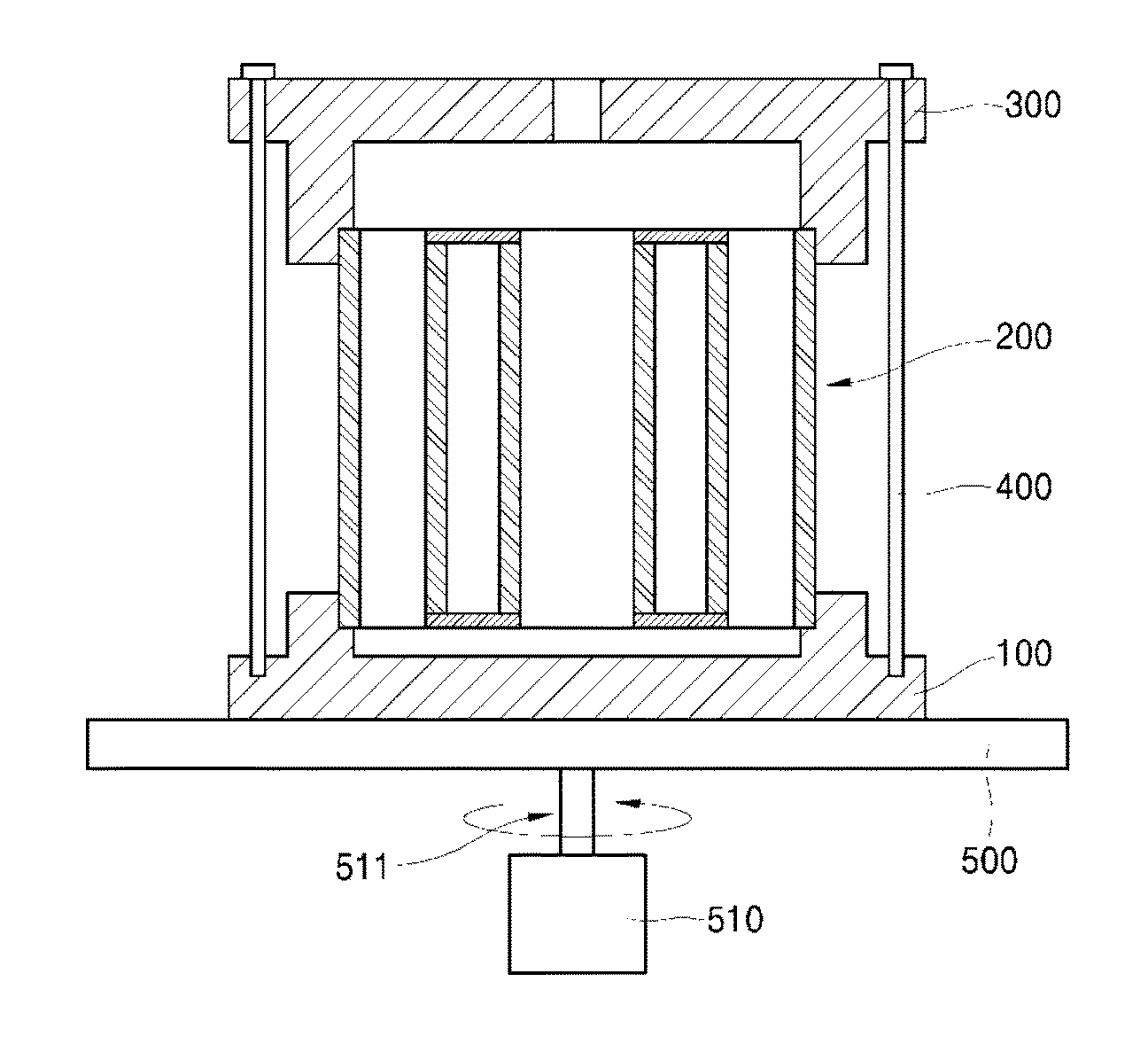
[0030]FIG. 1 is a flowchart of a method for centrifugal casting of a motor rotor in accordance with one embodiment of the present invention, and FIG. 2 is a view showing a process of preparing a lower mold in accordance with one embodiment of the present invention.

[0031]Referring to FIGS. 1 and 2, the method for centrifugal casting of a motor rotor according to one embodiment of the present invention includes mold / core assembly mold / core heating→forming

[0032]Mold / Core Assembly

[0033]Referring to FIGS. 1 to 4, the mold in accordance with one embodiment of the invention includes a lower mold 100 and an upper mold 300.

[0034]A core 200 may be secured to the lower mold 100. That is, a seating platform 110 is formed at an upper central portion of the lower mold 100, and the core 200 is seated on the sea...


PUM

PropertyMeasurementUnit
temperatureaaaaaaaaaa
shrinkageaaaaaaaaaa
densityaaaaaaaaaa

Abstract

Disclosed herein is a method for centrifugal casting of a motor rotor. The method includes: assembling molds and a core; heating the assembled mold and core to a preset temperature; and forming a motor core by injecting molten metal into a forming space inside the mold and the core while rotating the assembled mold.

Description

BACKGROUND[0001]1. Technical Field[0002]The present invention relates to a method for centrifugal casting of a motor rotor, and more particularly, to a method of centrifugally casting of a motor rotor which has less shrinkage, fewer pores and high density.[0003]2. Description of the Related Art[0004]In general, a motor or an induction motor includes a rotor rotating at the center thereof and a stator formed around the rotor.[0005]The rotor is formed at a center thereof with a hole into which a shaft is inserted, and includes a rotor core, which is constituted by a plurality of thin silicon steel plates stacked one above another.[0006]The rotor is formed with a plurality of slots penetrating the rotor core and having an arc shape, and is provided at both ends thereof with end rings, which electrically connect distal ends of a bar of the rotor to form a circuit.[0007]In the related art, rotors for small motors used in home appliances have been produced through centrifugal casting afte...

Claims


Application Information

Patent Timeline
Patent Type & Authority Applications(United States)
IPC IPC(8): B22D13/10H02K15/02B22D13/04
CPCB22D13/10H02K15/02B22D13/04H02K15/0012B22D13/101
Inventor LEE, SUNG-MOHAN, KWANG-JINYOO, JI-HOONLIM, JONG-WOOKYOON, YOUNG-CHEOL
Owner HYUNDAI HEAVY IND CO LTD
Learn More