
Charged filtration system

a filtration system and air particle technology, applied in the direction of magnetic separation, electric supply techniques, separation processes, etc., can solve the problems of reducing affecting the efficiency of air purification, and requiring regular cleaning, so as to reduce the cost, increase the efficiency of air purification, and increase the effect of occupancy turnover ra

Inactive Publication Date: 2015-12-03
RESTLESS NOGGINS DESIGN
View PDF16 Cites 13 Cited by
  • Summary
  • Abstract
  • Description
  • Claims
  • Application Information

AI Technical Summary

Benefits of technology

The present invention provides a charged particle filtration system that includes a replaceable charged filtration system that reduces costs and increases air purifying efficiency. The system is designed for use in locations that have traceable or even harmful amounts of bacteria, viruses, or germs in the air and have a high occupancy turnover rate, such as hospital rooms. The system allows for a frame to be placed into a hospital room, either permanently or semi-permanently, and a replaceable filter received in the frame to be replaced every time a new patient is admitted into that room. The replaceable filter reduces operating costs for the medical provider while ensuring that the air in the hospital or treatment room is sanitary for each occupying patient. The charged filtration system simultaneously filters air manually and electrically, and reduces ozone utilizing high air flow technology in a replaceable filter media. The media may have an antimicrobial agent to reduce costs and increases air purifying efficiency.

Problems solved by technology

However, in this advantage lies a disadvantage of precipitator type air filters.
The collector plates are difficult to maintain and require regular cleaning because they collect a large amount of fine dust.
Another disadvantage of the precipitator type filter is that they produce a significant amount of ozone.
A problem often arises with these home air filters because fibrous filter media can have high initial pressure or can block too much airflow as particles become trapped in the filter media.
Penultimately, this results in restricted airflow which ultimately causes damage to the equipment containing the filter.
To maintain the required airflow, the filters may require frequent filter replacement and the equipment may require frequent maintenance and cleaning.
This increases costs for owners utilizing this outdated technology.

Method used


Image

  • Charged filtration system
  • Charged filtration system
  • Charged filtration system

Examples


Embodiment Construction

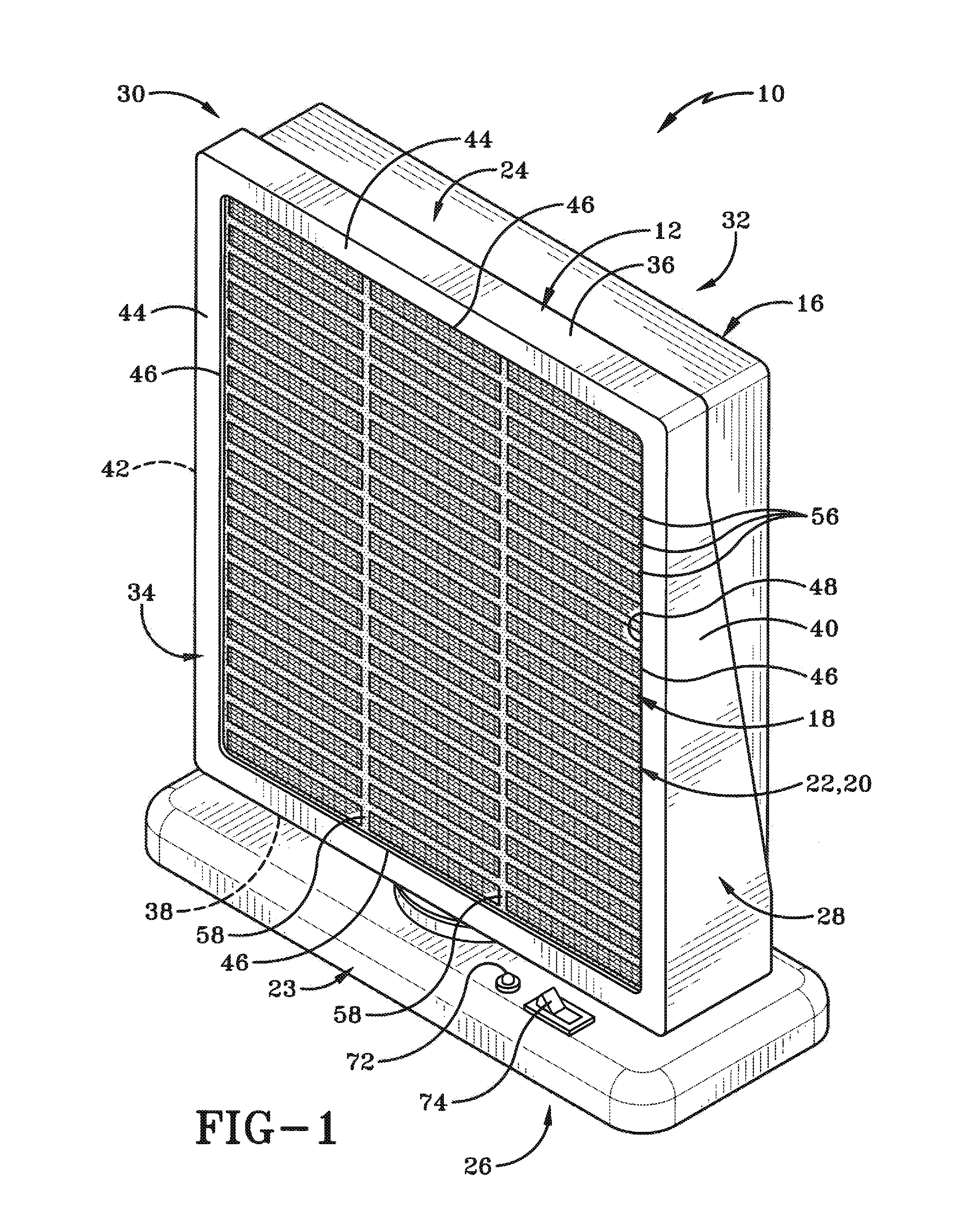
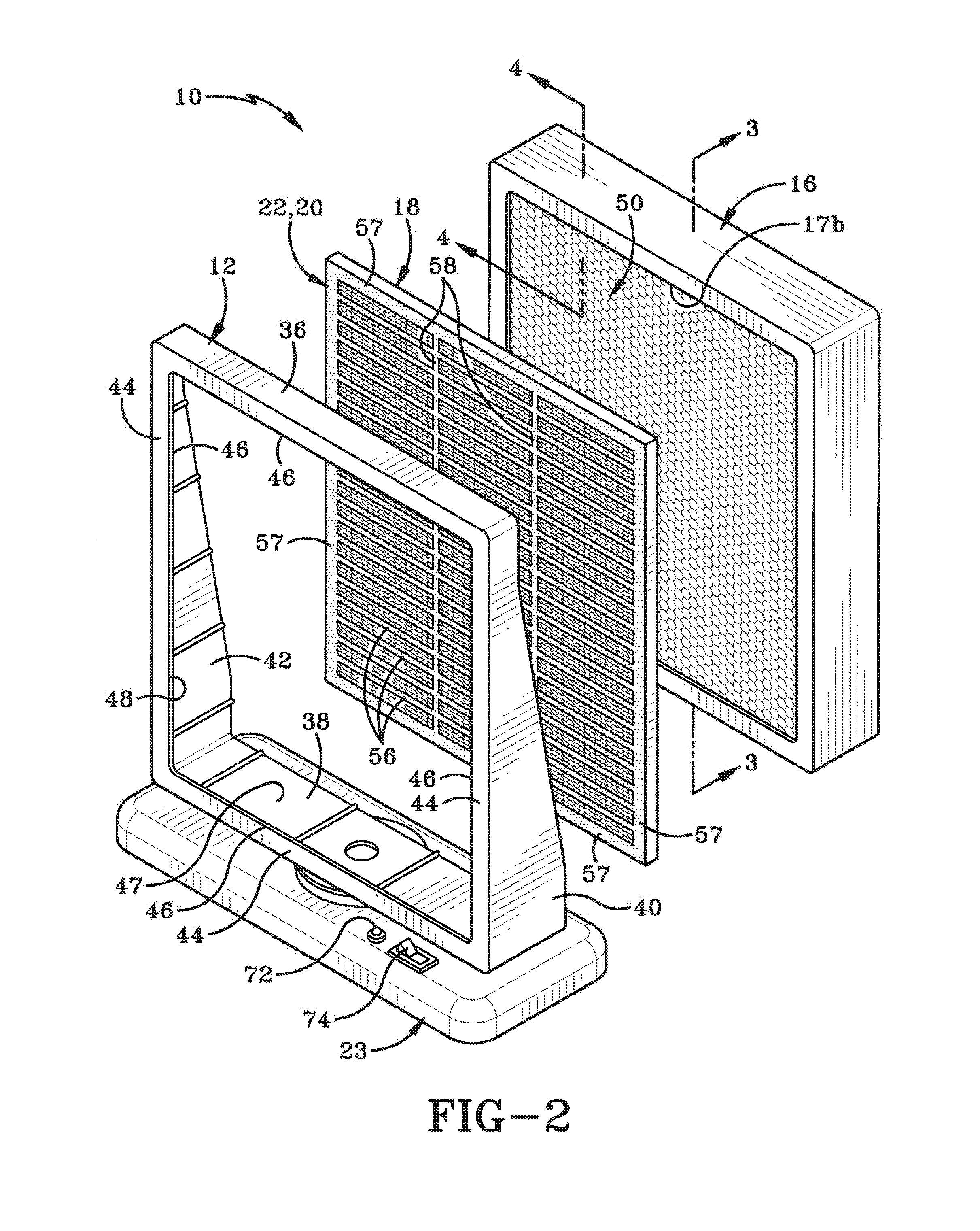
[0027]As shown in the FIGS. 1-2, the charged filtration system 10 of the present invention includes a frame 12, a corona wire 14 (FIG. 3) within a housing 16, a filter media 18, a conductive electrode 20 adjacent the filter media and an ozone filter 22 adjacent the conductive electrode 20 on the filter media 18. System 10 includes a top 24 and a bottom 26 that define therebetween a vertical direction. Frame 12 further includes a left side 28 and a right side 30 that define therebetween a lateral direction. Frame 12 further has a front end 32 and a rear end 34 that define therebetween a longitudinal direction. An airflow stream or pathway “F” extends longitudinally from front end 32 to rear end 34.

[0028]Frame 12 includes two vertically extending side walls 40, 42 which are spaced apart and preferably parallel to one another. Two horizontally extending and parallel side walls 36, 38 are spaced apart and intersect the two vertically extending side walls 40, 42 to form frame 12. Frame 1...


PUM

PropertyMeasurementUnit
diameteraaaaaaaaaa
air velocityaaaaaaaaaa
velocityaaaaaaaaaa

Abstract

A charged particle filtration system includes a replaceable charged filtration high air flow filter media, that may have an antimicrobial agent, to reduces costs and increases air purifying efficiency. The system is preferably used in locations that have traceable or even harmful amounts of bacteria, viruses, or germs in the air and have a high occupancy turnover rate, such as hospital rooms. The charged filtration system comprises the high air flow filter media and a conductive electrode array affixed to the high air flow filter media at one of the upstream surface and the downstream surface.

Description

BACKGROUND OF THE INVENTION[0001]1. Technical Field[0002]The present invention relates generally to filtration systems. More particularly, the present invention relates to charged air particle filtration systems. Specifically, the present invention relates to air filtration through the use of a high air flow filter media having a charged grid array attached thereto.[0003]2. Background Information[0004]It is understood in the fluid filtration field that charged particles can be readily recovered and filtered by a filter medium more effectively than neutral or uncharged particles. When used to filter air, these are known as ionizing air filters. One common ionizing air filter is a precipitator type. The precipitator type is an electronic air filter in which ionizing wires of about 0.005 inches diameter, charged at about 7 Kilovolts. These charged wires are placed between grounded plates to generate a corona. The corona charges dust particles as they are passed through the corona. Furt...

Claims


Application Information

Patent Timeline
Patent Type & Authority Applications(United States)
IPC IPC(8): B03C3/155B01D46/00B03C3/019B03C3/38
CPCB03C3/155B03C3/38B03C2201/26B03C3/019B01D46/0028B01D46/0032B01D46/50B03C3/09B03C3/12B03C3/41B03C3/47B03C3/66B03C2201/04
Inventor TYBURK, NEIL R.
Owner RESTLESS NOGGINS DESIGN
Learn More