Method for Regulating a Power Supply System

a power supply system and power supply technology, applied in transmission systems, dc source parallel operation, energy industry, etc., can solve the problems of decentralized power generation, less plannable energy production from wind power, solar energy and to a small extent also hydropower, and problems for the operation safety and reliability of the power grid. , to achieve the effect of simple and efficient, without major cost/complexity

Active Publication Date: 2015-11-26
SIEMENS AG
View PDF6 Cites 5 Cited by
  • Summary
  • Abstract
  • Description
  • Claims
  • Application Information

AI Technical Summary

Benefits of technology

The invention is a method for controlling a power grid by considering each supply level as an independent regulating unit. This allows for flexible and efficient control of the entire grid without major cost or complexity. The method also allows for the separation and operation of individual regulating units, which can act as stand-alone systems. The main technical effects of the invention include efficient and flexible control of the power grid, simplified and decentralized integration of distributed generation, and reduced data transfer between regulating units.

Problems solved by technology

However, alongside the advantage of preventing transformation losses, for example, decentralized power generation also has the disadvantage that energy production from wind power, solar energy and to a small extent also hydropower is much less plannable, e.g. because of weather-dependence, than e.g. power generation by means of conventional power plants.
This can result in considerable problems for the operational safety and reliability of the power grid.
However, the disadvantage of using a management system of this kind is its complex architecture, possibly involving major and expensive disruption to the existing structure of the power grid.
Moreover, it is questionable whether the use of such a management system is feasible at all for a relatively large power grid, as management is assumed centrally by a so-called cell controller.
The system disclosed in WO 2012 / 008979 A2 also has the disadvantage of a very complex and costly architecture, as a large number of control modules must be incorporated into the power grid.
In addition, the modules must be installed at great expense in the power grid, and adequate control involves monitoring and evaluating a large number of system parameters at different points in the grid.
A disadvantage common to the two systems disclosed in the respective publications is that they do not enable energy which is generated and fed in decentrally at the secondary distribution level, i.e. low-voltage level, to be controlled and regulated.

Method used


Image

  • Method for Regulating a Power Supply System
  • Method for Regulating a Power Supply System

Examples


Embodiment Construction

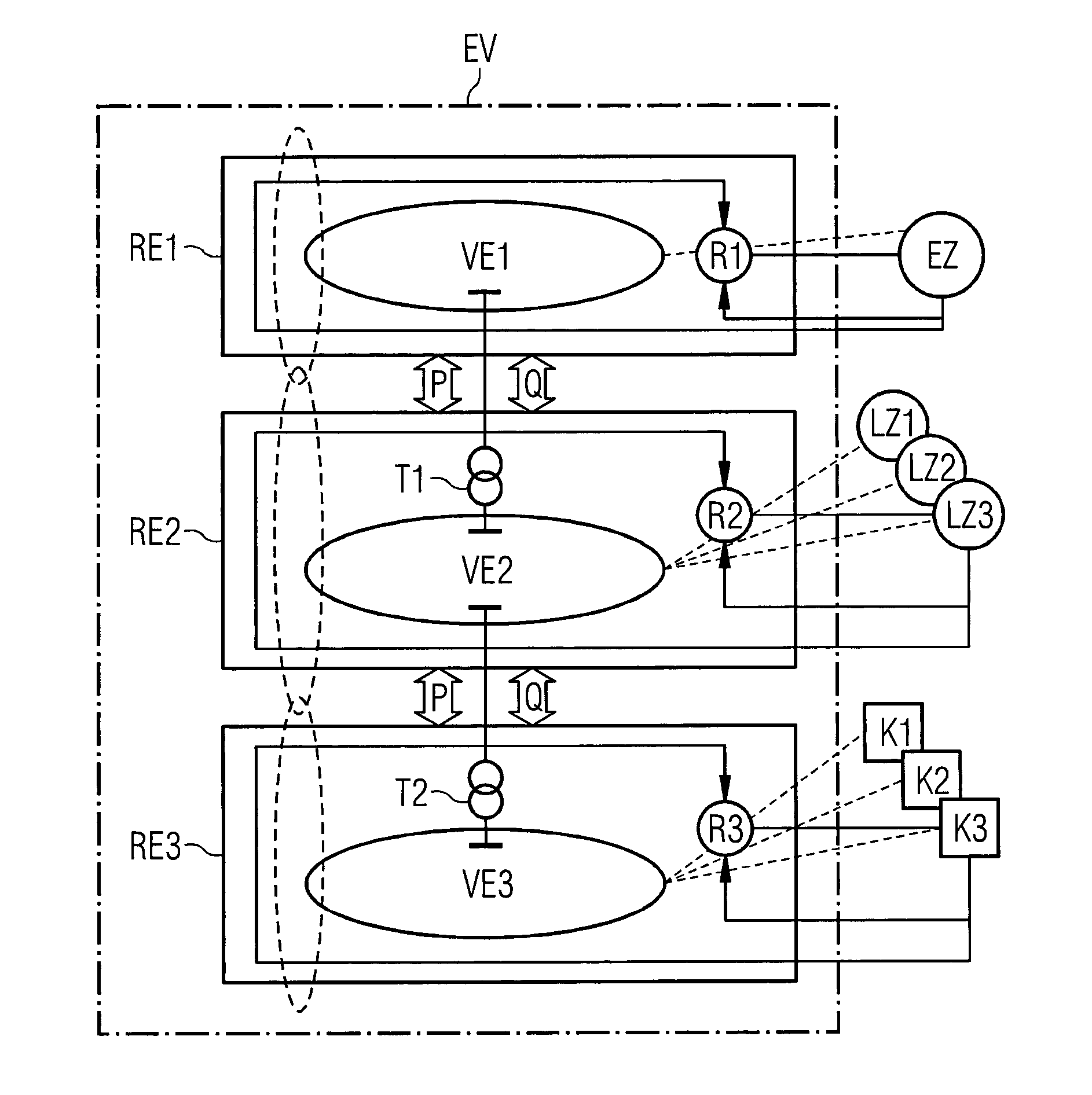
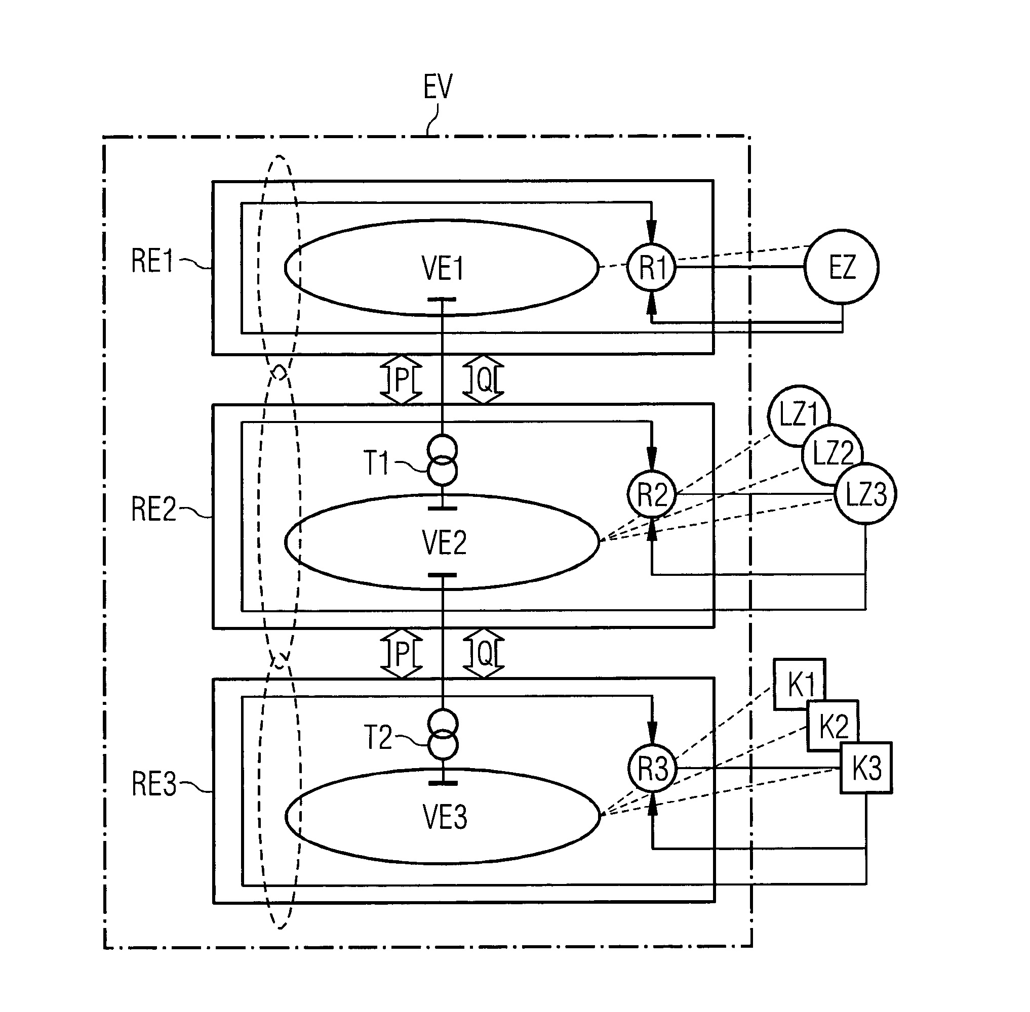
[0023]FIG. 1 schematically illustrates a typical power grid EV. This power grid EV has three supply levels VE1, VE2, VE3. A high-voltage transmission level is provided as the topmost or first supply level VE1. A second or middle supply level VE2 is implemented as a medium-voltage distribution level and a low-voltage or secondary distribution level is provided as the third or lowest supply level.

[0024]At each of these three supply levels VE1, VE2, VE3, energy is fed into the power grid EV decentrally via respective typical power generators EZ, LZ1, LZ2, LZ3, K1, K2, K3 at the respective supply level VE1, VE2, VE3. At the first supply level, i.e. the transmission level VE1, energy produced by large power generators EZ such as e.g. large hydroelectric power plants, thermal power plants or large wind farms is fed into the power grid. As well as larger consumers (e.g. factories, hospitals, etc.), regional or local power generators LZ1, LZ2, LZ3 such as e.g. small hydroelectric power plan...


PUM


Abstract

A method provides closed-loop control for an entire power supply system which has three supply levels each considered to be a separate regulatory unit and controlled independently of the other supply levels. An interface between two respective regulatory units is defined by control of the active power and reactive power transmitted between the two regulatory units. Appropriate control of the active power and reactive power transmitted between the regulatory units allows these regulatory units to be isolated from or connected to one another in terms of power. A power supply system is ideally regarded as a chain of separate regulatory units for supplying power. This allows efficient and safe operation and local control of a power supply system to which locally produced power is supplied, for example on different supply levels. In addition, a low number of data items to be interchanged between the supply levels is maintained.

Description

TECHNICAL FIELD[0001]The invention relates generally to the field of power grids. The present invention specifically relates to a method for regulating an entire power grid. Said power grid has three supply levels.BACKGROUND ART[0002]A power grid is usually understood as meaning a network of transmission lines in which physical processes can be described by what are known as Kirchhoff's laws, and by which energy or electricity is transported from energy producers (e.g. conventional power plant operators, etc.) and distributed to consumers (e.g. industrial concerns, homes, etc.). For this transportation, three supply levels which are in principle networks or network levels having different, defined voltage ranges are usually provided in a power grid. These supply levels are therefore classified according to the voltage range in which electrical energy is transmitted, and according to the corresponding distribution function. In a power grid there is usually a high-voltage or transmiss...

Claims


Application Information

Patent Timeline
IPC IPC(8): H02J4/00
CPCY10T307/352H02J4/00H02J3/06H02J2300/20H02J3/381Y02P80/10Y04S10/126Y02E60/00H02J3/388
Inventor ILO, ALBANA
Owner SIEMENS AG
Why Eureka
Try Eureka