
Apparatus and method for a global coordinate system for use in robotic surgery

Active Publication Date: 2015-11-26
AURIS HEALTH INC
View PDF11 Cites 295 Cited by
  • Summary
  • Abstract
  • Description
  • Claims
  • Application Information

AI Technical Summary

Benefits of technology

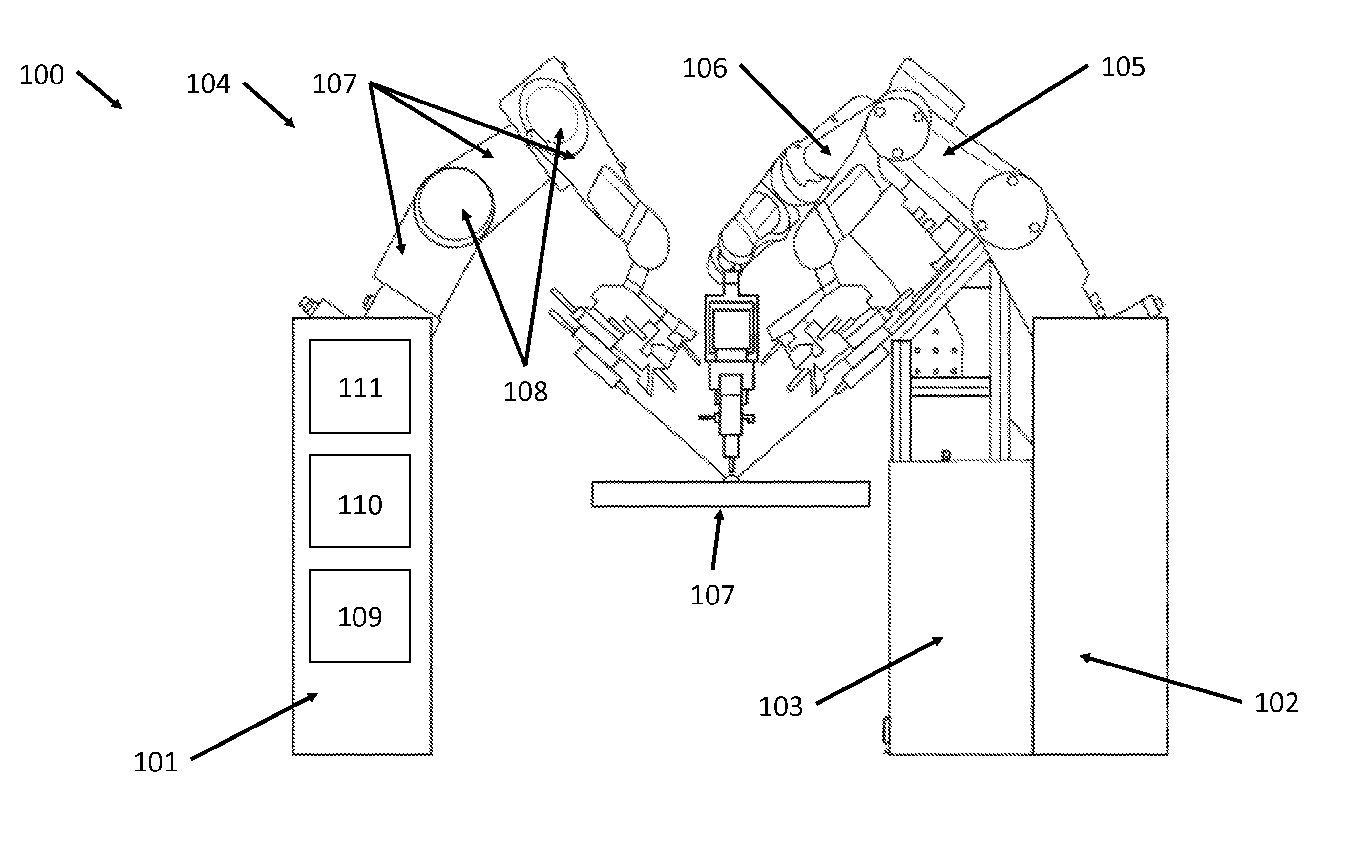
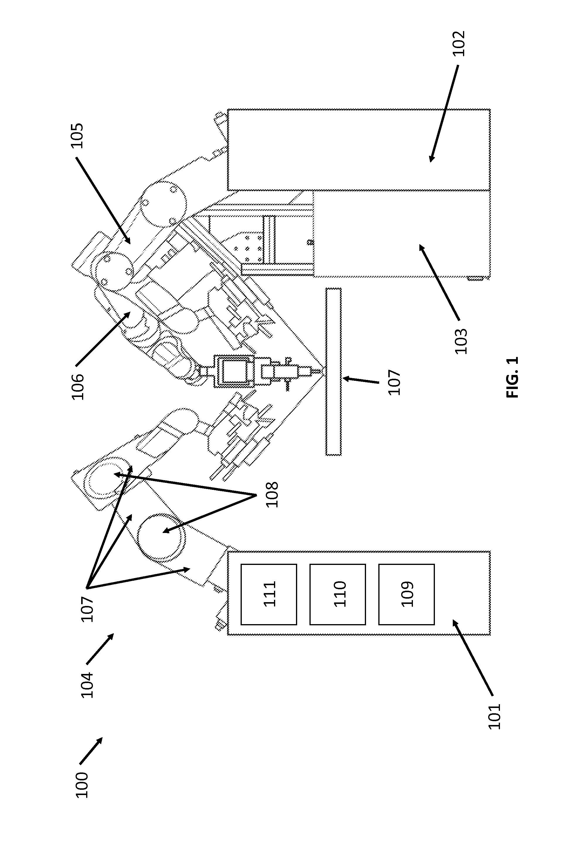
The present invention provides a method for robotic surgery using a global coordinate system. This involves registering the location of an optical assembly with a predetermined focal length that is operative with a mechanical arm, orienting the optical assembly over a patient's eye, registering the location of the patient's eye using the optical assembly, scanning the patient's eye using an optical tomographical system integrated into the optical assembly, retrieving optical tomopletional data, processing the data to create a three-dimensional model of the patient's eye, and integrating the three-dimensional model into a global coordinate system that has been registered to the location of the mechanical arm. This system allows for precise and safe surgical procedures using a robotic arm and optical tomography.

Problems solved by technology

Present microsurgical procedures are currently extremely technique dependent.
This propagation may lead to transmission of ultrasound energy along the probe to tissues in and around the eye that do not benefit from the transmission.
This places the lens capsule at risk for damage by this energy.
Finally, it may be quite difficult to steer an ultrasound probe around corners or bends, due to the mechanical requirements of propagating the ultrasound wave along the entire instrument.
They may generate unwanted heat in the eye and are often difficult to control, thus risking damage to important nearby tissues.
They also are easily damaged when attempting to navigate tight corners, as fibers in a laser probe may easily break.
However, these lasers can only fragment the center zone of the lens that is visible within the pupil (the iris blocks the peripheral lens from laser energy), so that fracture and removal of the peripheral lens by another method is still necessary.
They are costly to own and operate and have the additional drawback of extending operative time.

Method used


Image

  • Apparatus and method for a global coordinate system for use in robotic surgery
  • Apparatus and method for a global coordinate system for use in robotic surgery
  • Apparatus and method for a global coordinate system for use in robotic surgery

Examples


Embodiment Construction

[0029]Although certain preferred embodiments and examples are disclosed below, inventive subject matter extends beyond the specifically disclosed embodiments to other alternative embodiments and / or uses, and to modifications and equivalents thereof. Thus, the scope of the claims appended hereto is not limited by any of the particular embodiments described below. For example, in any method or process disclosed herein, the acts or operations of the method or process may be performed in any suitable sequence and are not necessarily limited to any particular disclosed sequence. Various operations may be described as multiple discrete operations in turn, in a manner that may be helpful in understanding certain embodiments; however, the order of description should not be construed to imply that these operations are order dependent. Additionally, the structures, systems, and / or devices described herein may be embodied as integrated components or as separate components.

[0030]For purposes of...


PUM


Abstract

An apparatus and method for establishing a global coordinate system to facilitate robotic assisted surgery. The coordinate system may be established using a combination of the robotic data, i.e., kinematics, and optical coherence tomographic images generated by an overhead optical assembly and a tool-based sensor. Using these components, the system may generate a computer-registered three-dimensional model of the patient's eye. In some embodiments, the system may also generate a virtual boundary within the coordinate system to prevent inadvertent injury to the patient.

Description

CROSS-REFERENCE TO RELATED APPLICATIONS[0001]This application is a continuation-in-part of U.S. patent application Ser. No. 13 / 868,769 (Attorney Docket No. 41663-704.201), filed Apr. 23, 2013, which claims priority from U.S. Provisional Application No. 61 / 637,426 (Attorney Docket No. 41663-704.101), filed Apr. 24, 2012, the entire contents of which are incorporated by reference.BACKGROUND OF THE INVENTION[0002]1. Field of the Invention The field of the present application pertains to medical devices. More particularly, the field of the invention pertains to an apparatus and method for a global coordinate system for use in robotic-assisted surgery.[0003]Embodiments described herein are directed to a new method, apparatus, and system for generating and operating a global coordinate system that may be useful for performing robotically-assisted surgery.[0004]2. Description of the Related Art. Present microsurgical procedures are currently extremely technique dependent. For example, seve...

Claims


Application Information

Patent Timeline
IPC IPC(8): A61F9/007A61B3/10A61B3/13A61B19/00
CPCA61F9/00736A61B19/2203A61B19/5223A61B3/13A61B2019/5234A61B3/102A61B2090/3735A61B34/30A61B90/03A61B5/0059A61B5/0066A61B2034/105A61B2034/2055A61B2090/066
Inventor ALVAREZ, JEFFERY B.ZHANG, JIANKINTZ, GREGORY
Owner AURIS HEALTH INC
Learn More