Cargo bay construction with a slideable wall and vehicle with such a cargo bay construction
- Summary
- Abstract
- Description
- Claims
- Application Information
AI Technical Summary
Benefits of technology
Problems solved by technology
Method used
Image
Examples
Embodiment Construction
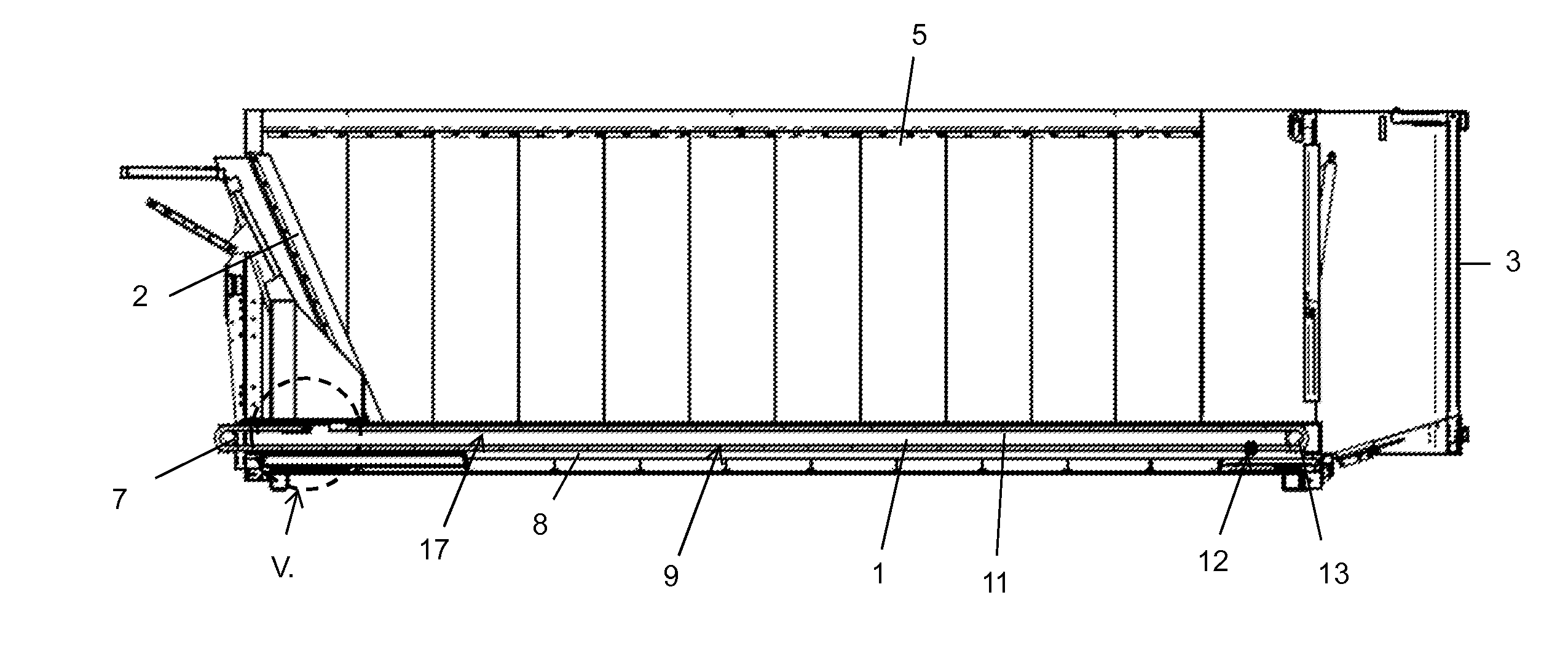
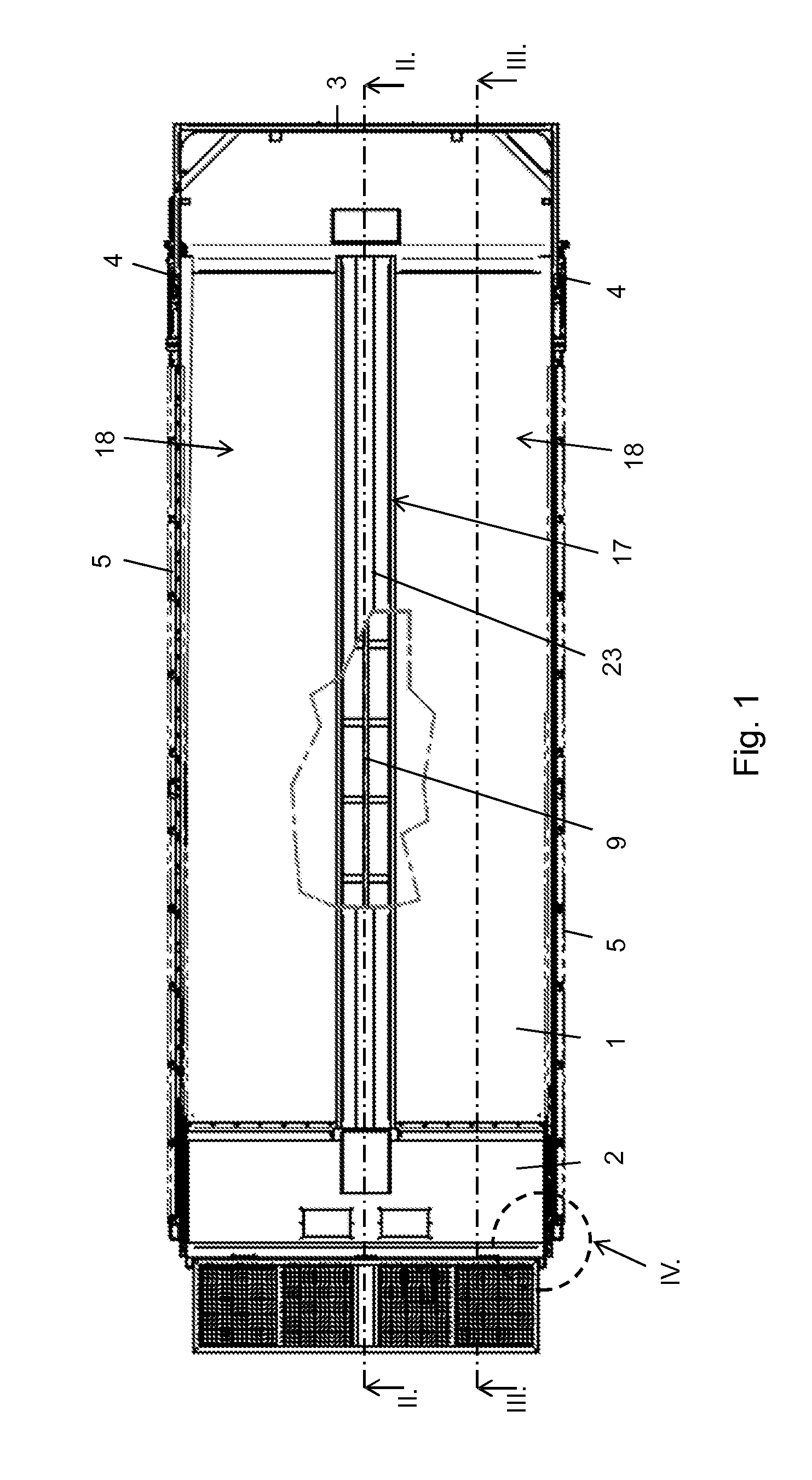
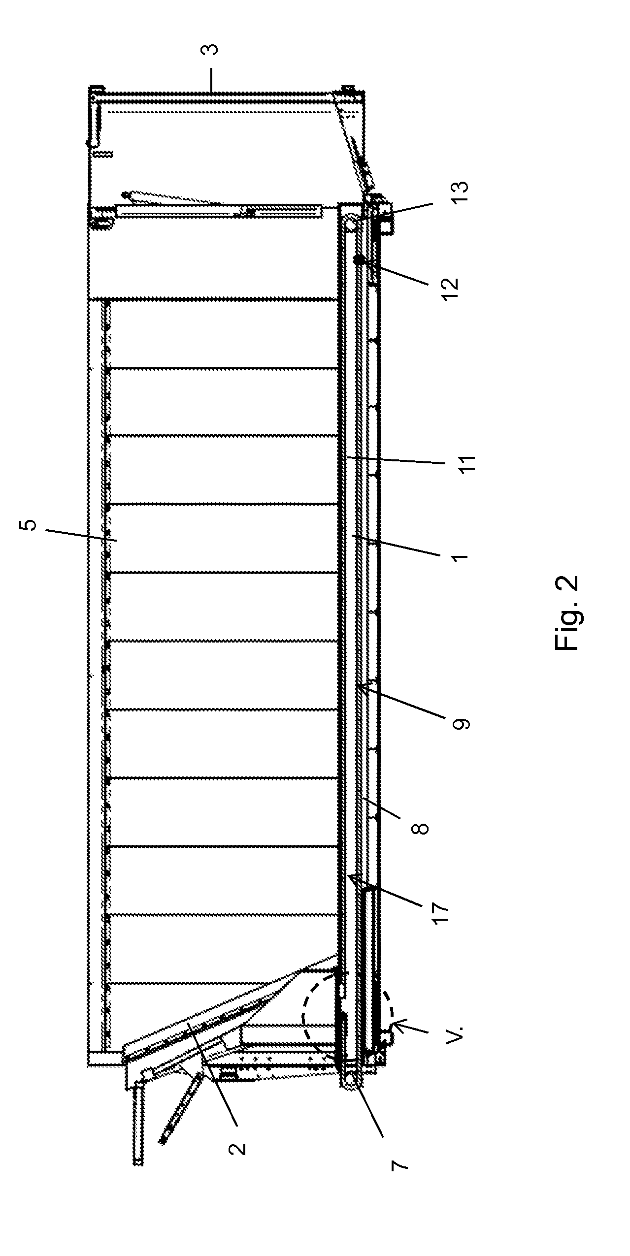
[0033]The cargo bay construction represented in the drawings encompasses a floor 1, as well as the adjacent walls at the end of the floor 1, that limit the upwardly open cargo bay. It is seen in a longitudinal direction of the cargo bay construction, that an anterior front wall 2 is moved by being slid, while a back wall 3 is moved upwardly on hinges of the swivel joints 4, in order to provide unloading openings. Additionally, two fixed walls 5 are still designed.
[0034]The front wall 2 is moved by being slid on the floor 1 along the longitudinal direction of the cargo bay construction, whereby the volume of the cargo bay can be changed. This can then be used to unload a stored load in the cargo bay from the opened back wall 3 over the unloading opening, which in comparison to tip troughs, can take place relatively constantly. The load can be sealed through the sliding of the front wall 2, which can be particularly designed for the closed back wall 3. FIGS. 1 to 3 show the front wall...
PUM
 Abstract
Description
Claims
Application Information
 - R&D
- Intellectual Property
- Life Sciences
- Materials
- Tech Scout
- Unparalleled Data Quality
- Higher Quality Content
- 60% Fewer Hallucinations
Browse by: Latest US Patents, China's latest patents, Technical Efficacy Thesaurus, Application Domain, Technology Topic, Popular Technical Reports.
© 2025 PatSnap. All rights reserved.Legal|Privacy policy|Modern Slavery Act Transparency Statement|Sitemap|About US| Contact US: help@patsnap.com


