
Insulating coated wire and method for manufacturing the same

a technology manufacturing method, which is applied in the direction of insulating conductors/cables, cables, insulated conductors, etc., can solve the problems of inability to achieve improvement in wiring operation efficiency, difficulty in wiring operation, and inability to easily bend, so as to facilitate bending of insulating coated wire, and facilitate the effect of insulating coated

Active Publication Date: 2015-10-29
AUTONETWORKS TECH LTD +2
View PDF6 Cites 3 Cited by
  • Summary
  • Abstract
  • Description
  • Claims
  • Application Information

AI Technical Summary

Benefits of technology

The present invention provides an insulating coated wire that is easy to bend without complicated structures and methods. The insulating coating includes a bending auxiliary section that is thinner and shaped to facilitate bending. The wire can be easily manufactured using a metal mold and a pressure difference between the inside and outside of the insulating coating. The technical effect is to make an insulating coated wire that is easy to bend and a method for manufacturing it.

Problems solved by technology

However, an electrical wire that has so large a diameter that a high current flows therethrough, such as an electrical wire that connects battery terminals arranged close to each other, has the problem of not being able to easily be bent due to the high hardness of an insulating coating, and making the wiring operation difficult.
It is significantly troublesome to perform these operations at a place at which wiring is performed, and an improvement in efficiency of the wiring operation cannot be expected to be achieved.
Such a disadvantage becomes more serious as the electrical wire has greater number of portions to be bent.

Method used


Image

  • Insulating coated wire and method for manufacturing the same
  • Insulating coated wire and method for manufacturing the same
  • Insulating coated wire and method for manufacturing the same

Examples


Embodiment Construction

[0016]The preferred embodiment of the present invention will be described with reference to the drawings.

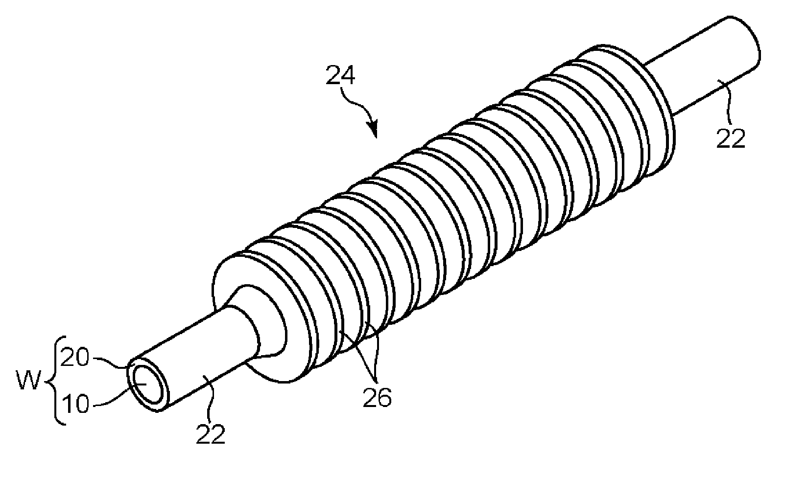
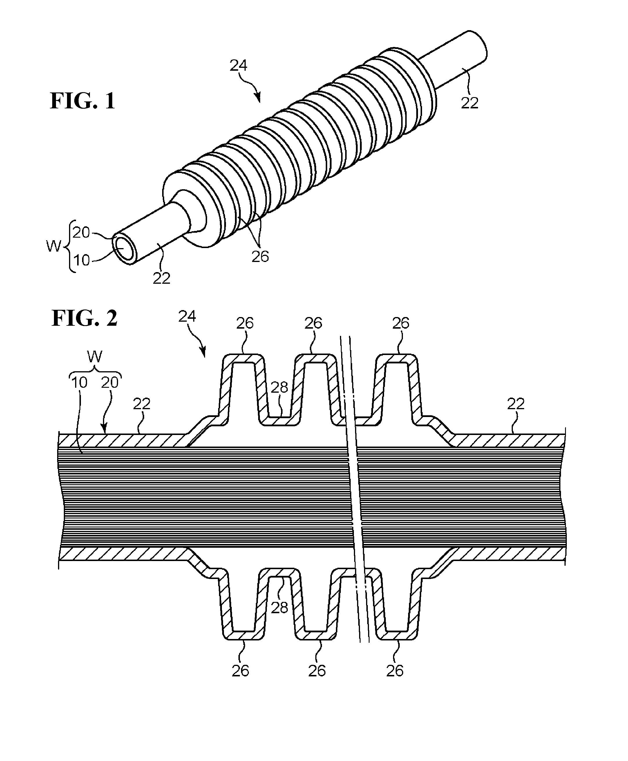
[0017]FIGS. 1 and 2 show an insulating coated wire W according to the present invention. This insulating coated wire W includes a center conductor 10, and an insulating coating 20 that covers the center conductor 10. Any material that has a high conductivity can be used for the center conductor 10, and the center conductor 10 is constituted, for example, by a single or a plurality of bare wires that are made of a metal material such as copper that has an excellent conductivity. The insulating coating 20 is made of an insulating synthetic resin material.

[0018]This insulating coated wire W is characterized in that the insulating coating 20 has a bending auxiliary section 24 at a part in the axial direction thereof. This bending auxiliary section 24 is different in shape from the section of the insulating coating 20 that is other than the bending auxiliary section 24, that is, a nor...


PUM

PropertyMeasurementUnit
softening temperatureaaaaaaaaaa
circumferenceaaaaaaaaaa
pressureaaaaaaaaaa

Abstract

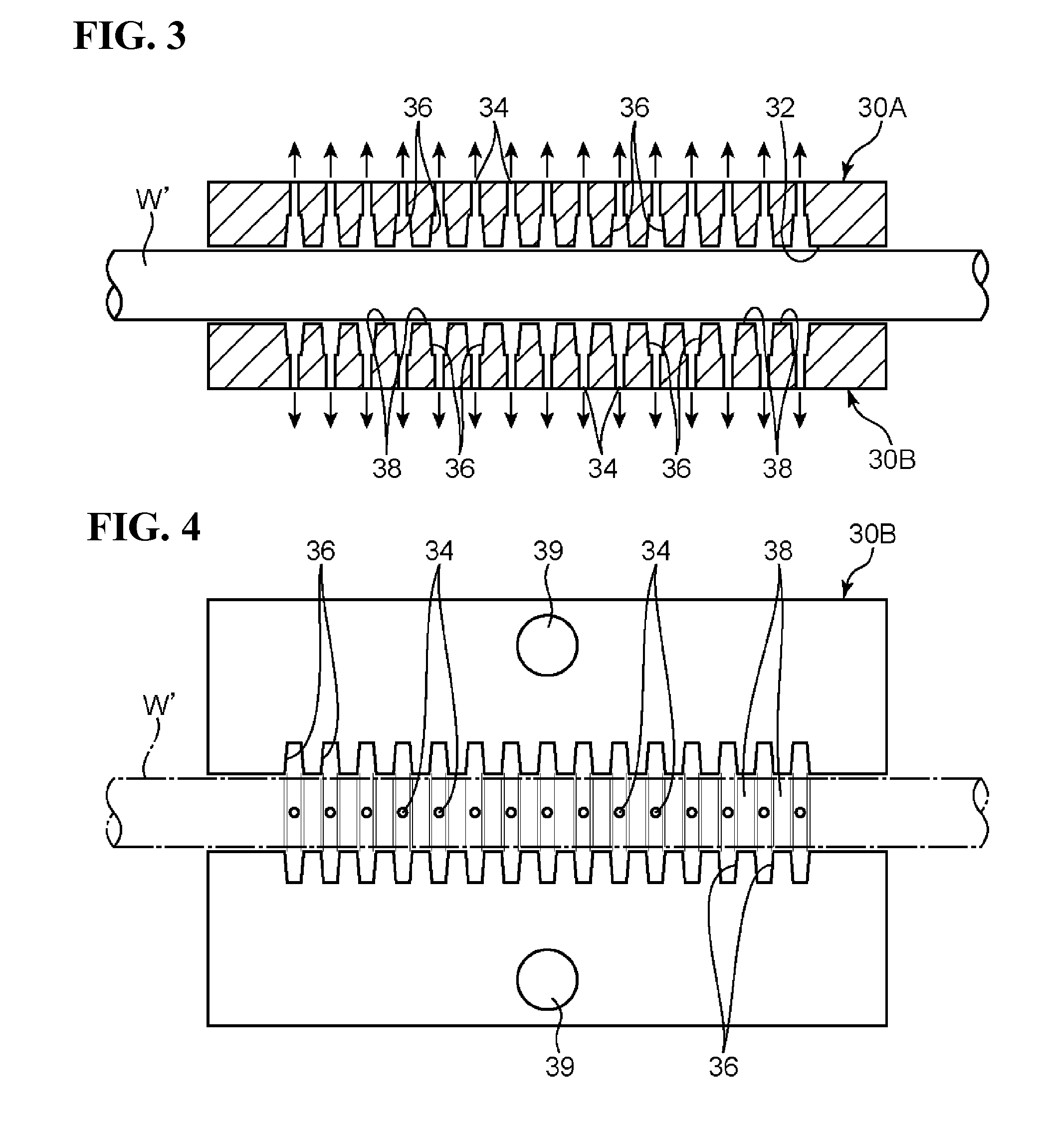
An insulating coated wire includes a center conductor and an insulating coating. The insulating coating has a bending auxiliary section in which the thickness of the insulating coating is smaller than that of the other portion, and that has a shape in which at least a part thereof protrudes outward in the radial direction. The bending auxiliary section has a shape that facilitates bending of the insulating coated wire by elongation deformation thereof. This insulating coated wire can be manufactured by arranging, on the circumference of an insulating coated wire material, a metal mold that has the inner surface including the section having a shape protruding outward in the radial direction, and forming the bending auxiliary section in the shape along the inner surface of the metal mold by heating the insulating coating within the metal mold and generating a pressure difference between inside and outside of the insulating coating.

Description

TECHNICAL FIELD[0001]The present invention relates to an insulating coated wire that is to be arranged in an automobile or the like, and a method for manufacturing the same.BACKGROUND ART[0002]An insulating coated wire includes a center conductor and an insulating coating that covers the center conductor. When such an insulating coated wire is arranged in an automobile or the like, the insulating coated wire is used while being bent at an appropriate position into the shape that is suitable for the arrangement position. However, an electrical wire that has so large a diameter that a high current flows therethrough, such as an electrical wire that connects battery terminals arranged close to each other, has the problem of not being able to easily be bent due to the high hardness of an insulating coating, and making the wiring operation difficult.[0003]As means for solving this problem, Patent Document 1 discloses a method including the steps of removing a coating material from a port...

Claims


Application Information

Patent Timeline
Patent Type & Authority Applications(United States)
IPC IPC(8): H01B3/30H01B13/06B29C49/20H01B3/44B29C48/12B29C48/154
CPCH01B3/302H01B3/44H01B3/307H01B13/06B29C49/20B29C2049/2021B29L2031/3462B29K2705/00B29K2715/00B29K2995/0007B29L2009/003B29L2009/005B29K2101/12H01B7/24B29L2023/183B29C51/10B29C51/12H01B13/0009B29C48/154B29C48/12B29D23/005
Inventor MIZUNO, HOUSEIHIRAI, HIROKISAKATA, TOMOYUKIHOSOKAWA, TAKEHIROOOTSUKA, YASUYUKIMURAO, SATOSHINAKANO, SEIGOU
Owner AUTONETWORKS TECH LTD
Learn More