Eureka AIR delivers breakthrough ideas for toughest innovation challenges, trusted by R&D personnel around the world.

Massage Table System and Method

a massage table and massage technology, applied in the field of massage table systems and methods, to achieve the effect of precise horizontal placement speed control

Inactive Publication Date: 2015-10-29
ONEAL COLBY HARPER
View PDF11 Cites 10 Cited by
  • Summary
  • Abstract
  • Description
  • Claims
  • Application Information

AI Technical Summary

Benefits of technology

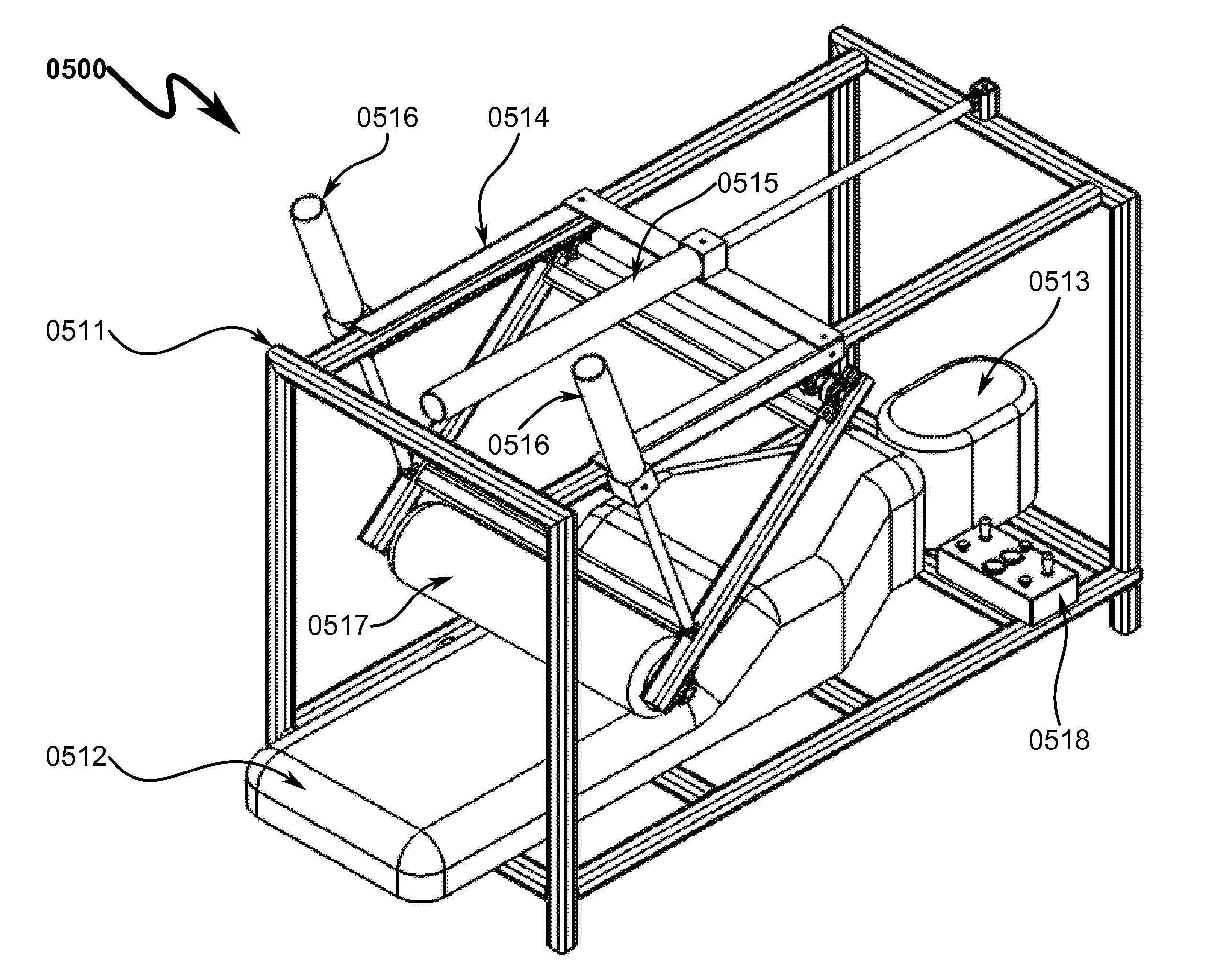
The patent describes a massage device for prone-positions patients that allows for precise horizontal movement and control of massage pressure. The device includes a patient massage roller and a horizontal slide assembly that moves across the patient's body. The speed and pressure of the massage can be controlled by the patient or therapist through adjustment of a pneumatic regulator or manual valve. The device also includes a control interface box for easy adjustment by either the patient or therapist. Overall, the device allows for safer and more effective massage therapy for prone-positions patients.

Problems solved by technology

Although many prior art methods and devices provide some degree of deep tissue therapy, none offer the advantages of a coordinated massage that includes compression and stretching.
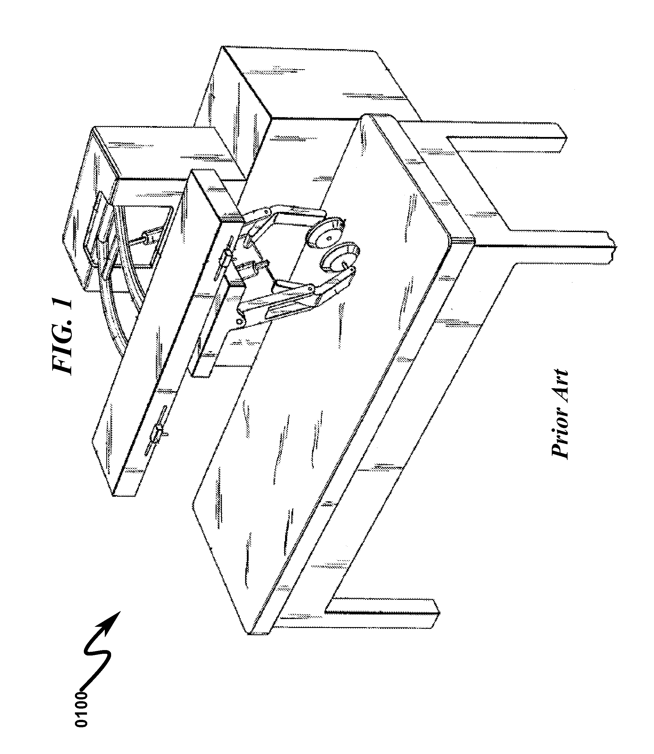
Disadvantages to this architecture include:Higher pressure can lift the patient body;Inability to apply static pressure;Contact point continually changes; andSmall contact point (may only use narrow rollers because the patient's body has to be supported by the table).
However, this system suffers from the following deficiencies:Pneumatic cylinders are not controllable in this design and thus there is no methodology of controlling the pressure exerted on the patient.Table is not integrated into the overall massage system and therefore the system is not portable or amenable to space-constrained environments.Patient is not in control of the massage operation.
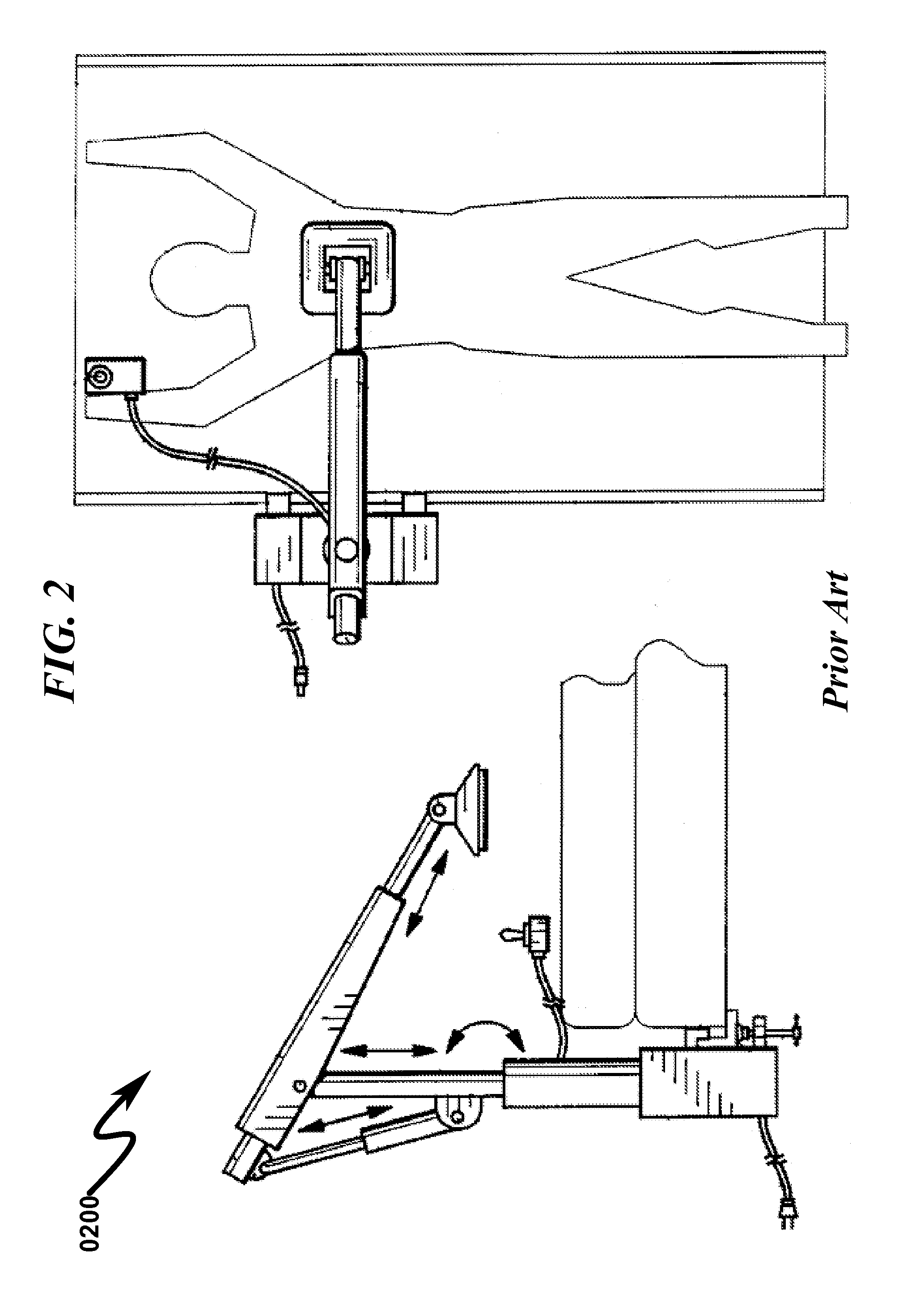
As generally illustrated in FIG. 2 (0200), U.S. Pat. No. 4,984,568 (circa 1991) illustrates a massage table with the patient facing down but lacks a coordinated control and monitoring system to provide for repeatable massage treatments to the patient.
A major deficiency in this design is the inability to control the pressure applied to the patient during the massage treatments.
The prior art as detailed above suffers from the following deficiencies:The prior art lacks the ability to apply compression and stretching with the same treatment.The prior art lacks the ability to enable the patient or therapist to perform the massage.The prior art lacks the ability to monitor the pressure applied to the patient.The prior art lacks the ability to automatically repeat massage therapy treatments.The prior art lacks the ability to automatically record massage therapy treatments for reuse on the same patient.The prior art lacks the ability to store and retrieve prerecorded massage therapy treatments for use on the patients.The prior art lacks the ability to apply controlled and monitored static pressure to a patient.The prior art lacks the ability to vary the applied pressure from very light to deep within a given treatment program.The prior art lacks the ability to vary the speed of the treatment program from slow to fast.The prior art lacks the ability to apply treatment to a large area body contact point.The prior art lacks the ability to accommodate various sized patients.
While some of the prior art may teach some solutions to several of these problems, the core deficiencies in the prior art systems have not been addressed.

Method used


Image

  • Massage Table System and Method
  • Massage Table System and Method
  • Massage Table System and Method

Examples


Embodiment Construction

[0131]While this invention is susceptible of embodiment in many different forms, there is shown in the drawings and will herein be described in detailed preferred embodiment of the invention with the understanding that the present disclosure is to be considered as an exemplification of the principles of the invention and is not intended to limit the broad aspect of the invention to the embodiment illustrated.

[0132]The numerous innovative teachings of the present application will be described with particular reference to the presently preferred embodiment, wherein these innovative teachings are advantageously applied to the particular problems of a MASSAGE TABLE SYSTEM AND METHOD. However, it should be understood that this embodiment is only one example of the many advantageous uses of the innovative teachings herein. In general, statements made in the specification of the present application do not necessarily limit any of the various claimed inventions. Moreover, some statements ma...


PUM


Abstract

A massage table system / method allowing self-application of adjustable compression and stretching is disclosed. The system incorporates a frame support structure (FSS) horizontally supporting a patient support table (PST) and patient face cradle (PFC) permitting a massage patient to receive adjustable massage from a body contact assembly (BCA) positioned using a horizontal slide assembly (HSA) under pneumatic control of a horizontal cylinder assembly (HCA). The patient is massaged via a patient massage roller (PMR) radially articulated by the BCA in response to pneumatic pressure applied by a vertical cylinder assembly (VCA) while the BCA is positioned longitudinally over the patient by the HSA. A control interface box (CIB) provides adjustment of HSA travel speed, position, and applied pressure to the PMR by the VCA. Computer controls within the CIB may permit automated patient massage procedures by pre-programmed / memorized operation of pneumatic valves controlling the HSA and BCA.

Description

CROSS REFERENCE TO RELATED APPLICATIONS[0001]Not ApplicablePARTIAL WAIVER OF COPYRIGHT[0002]All of the material in this patent application is subject to copyright protection under the copyright laws of the United States and of other countries. As of the first effective filing date of the present application, this material is protected as unpublished material.[0003]However, permission to copy this material is hereby granted to the extent that the copyright owner has no objection to the facsimile reproduction by anyone of the patent documentation or patent disclosure, as it appears in the United States Patent and Trademark Office patent file or records, but otherwise reserves all copyright rights whatsoever.STATEMENT REGARDING FEDERALLY SPONSORED RESEARCH OR DEVELOPMENT[0004]Not ApplicableREFERENCE TO A MICROFICHE APPENDIX[0005]Not ApplicableFIELD OF THE INVENTION[0006]The present invention generally relates to systems and methods for providing therapeutic massage. While not limitive ...

Claims


Application Information

Patent Timeline
IPC IPC(8): A61H15/00
CPCA61H15/00A61H15/0078A61H2015/0014A61H2015/0035A61H2201/1246A61H2201/1623A61H2201/1628A61H2201/164A61H2201/1666A61H2201/1669A61H2201/5035A61H2201/5038A61H2201/5056A61H2201/5071A61H2203/0468A61H2205/081A61H2205/086A61H2205/10
Inventor O'NEAL, COLBY HARPER
Owner ONEAL COLBY HARPER
Why Eureka
Eureka Blog
Learn More