
Display Device Integrated with Touch Screen Panel and Method of Driving the Same

a technology of touch screen and display device, which is applied in the direction of instruments, computing, electric digital data processing, etc., can solve the problems of increasing load, lowering touch sensing accuracy, and unsatisfactory parasitic capacitance generation, so as to reduce load, prevent parasitic capacitance, and reduce the accuracy of touch sensing

Active Publication Date: 2015-10-22
LG DISPLAY CO LTD
View PDF1 Cites 11 Cited by
  • Summary
  • Abstract
  • Description
  • Claims
  • Application Information

AI Technical Summary

Benefits of technology

The present patent provides a display device with a touch screen panel that can prevent unwanted electrical effects during touch operation, which can lower touch sensing accuracy. This technology prevents the display from becoming incessantly powered during touch, reducing the strain on the device's battery and ensuring consistent touch sensing.

Problems solved by technology

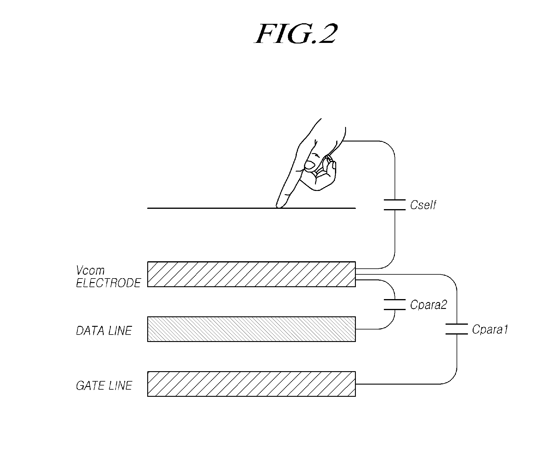
According to the capacitive touch sensing technology, in addition to capacitance necessary for touch sensing, undesirable parasitic capacitance is generated by other voltage lines or electrodes around the touched electrode(s).
The undesirable parasitic capacitance causes certain problems, for example, increasing the load during a touch operation, lowering the accuracy of touch sensing, and in severe cases, making touch sensing impossible.
The problems caused by undesirable parasitic capacitance are more severe in medium-sized or large displays.
In addition, the problems caused by the undesirable parasitic capacitance frequently occur in display devices integrated with a touch screen panel (TSP) in which an in-cell touch screen panel is embedded in a display panel.
These problems make it difficult or impossible to produce middle-sized or larger in-cell touch screen panels.

Method used


Image

  • Display Device Integrated with Touch Screen Panel and Method of Driving the Same
  • Display Device Integrated with Touch Screen Panel and Method of Driving the Same
  • Display Device Integrated with Touch Screen Panel and Method of Driving the Same

Examples


Embodiment Construction

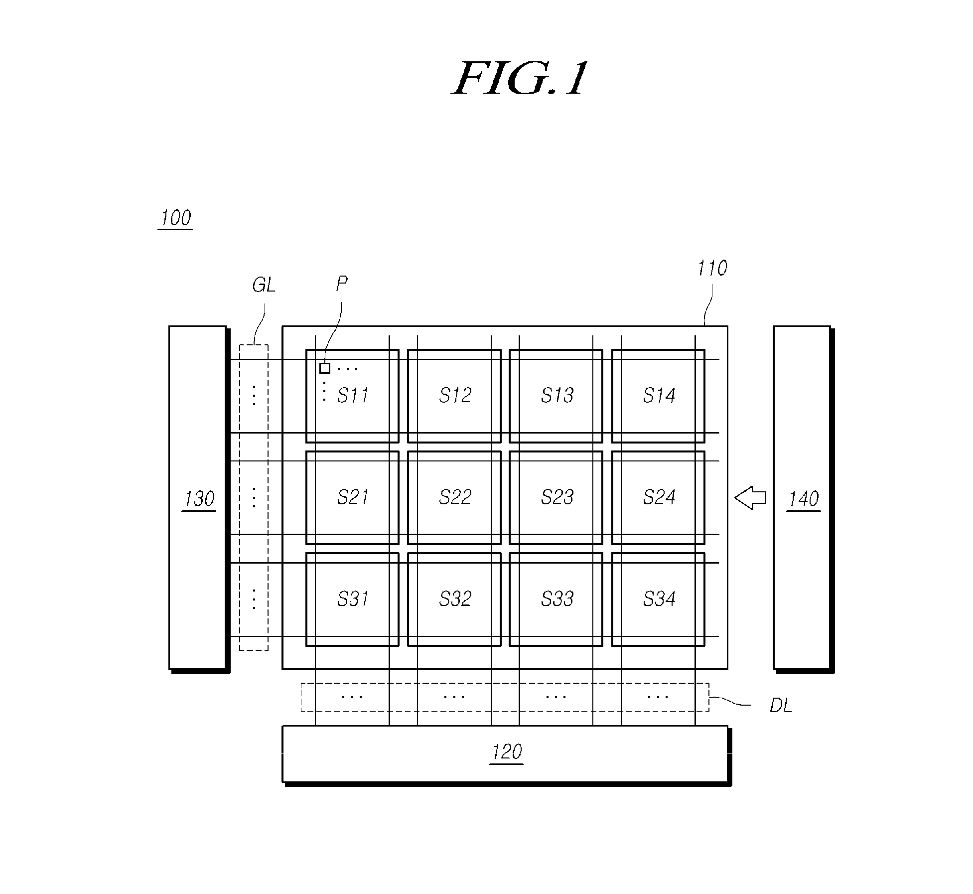
[0043]Reference will now be made in detail to the present disclosure, embodiments of which are illustrated in the accompanying drawings. Throughout this document, reference should be made to the drawings, in which the same reference numerals and signs may be used throughout the different drawings to designate the same or similar components. In the following description of the present disclosure, detailed descriptions of known functions and components incorporated herein will be omitted when they may make the subject matter of the present disclosure unclear.

[0044]It will be understood that, although terms “first,”“second,”“A,”“B,”“(a),”“(b),” etc. may be used herein to describe various elements, these terms are only used to distinguish one element from another element. The substance, sequence, order or number of these elements are not limited by these terms. It will be understood that when an element is referred to as being “connected to” or “coupled to” another element, not only can...


PUM


Abstract

A display device integrated with a touch screen panel, and a method of driving the same, can prevent parasitic capacitance that would otherwise increase the load during a touch operation, lower the accuracy of touch sensing, or make touch sensing impossible. The display device includes data lines, gate lines, and a plurality of electrodes spaced apart from each other. A common voltage is applied to the electrodes in a display driving mode and a touch drive signal is applied to one or more of the electrodes in a touch driving mode. A data voltage is applied to the data lines in the display driving mode. A scan signal is supplied sequentially to the gate lines in the display driving mode and the touch drive signal or a signal corresponding to the touch drive signal is applied to one or more of the gate lines in the touch driving mode.

Description

CROSS REFERENCE TO RELATED APPLICATION[0001]This application is a continuation application under 35 U.S.C. §120 of U.S. patent application Ser. No. 14 / 476,277 filed on Sep. 3, 2014, which claims priority from and the benefit under 35 U.S.C. §119(e) of U.S. Patent Application No. 61 / 919,118 filed on Dec. 20, 2013, and under 35 U.S.C. §119(a) of Korean Patent Application Number 10-2014-0006350 filed on Jan. 17, 2014, which are hereby incorporated by reference for all purposes as if fully set forth herein.BACKGROUND[0002]1. Technical Field[0003]The present disclosure relates to a display device integrated with a touch screen panel and a method of driving the same.[0004]2. Description of Related Art[0005]In response to the development of the information society, there is increasing demand for various types of display devices which display images. Currently, various display devices such as liquid crystal displays (LCDs), plasma display panels (PDPs) and organic light-emitting diode displ...

Claims


Application Information

Patent Timeline
Patent Type & Authority Applications(United States)
IPC IPC(8): G06F3/041
CPCG06F3/041G06F3/0412G06F3/0418G06F3/04166G06F3/0446G06F3/044G09G3/2096G09G2300/043G09G2310/0208G09G2310/0213G09G2310/08G09G2330/02
Inventor SHIN, SEUNGROKLEE, DEUKSU
Owner LG DISPLAY CO LTD
Learn More