Multi-track adjustable golf club

a golf club and adjustable technology, applied in the field of golf clubs, can solve the problems of golfer's swing, golf club may no longer be suitable for golfers, and clubs cannot be easily modified to compensa

Active Publication Date: 2015-10-22
MIZUNO USA
View PDF18 Cites 84 Cited by
  • Summary
  • Abstract
  • Description
  • Claims
  • Application Information

AI Technical Summary

Benefits of technology

[0012]Embodiments of the present disclosure relate to an adjustable golf club. In some embodiments, the club can be adjusted by adding weights to tracks located on the sole of the club in predetermined locations. An adjustable golf club according to the present disclosure can have a club head having a sole and a ball-striking face. The sole of the golf club head can include two or more tracks located on the sole such that each track can receive at least one weight.
[0013]In some embodiments, the two or more tracks can comprise an elongated central track, a first short track disposed on a first side of the elongated central track, and a second short track disposed on the second side of the elongated central track. In some embodiments, the first and second short tracks can be evenly spaced on either side of the elongated central track. In some embodiments, the two short tracks can be configured to accept a weight in only one position. In some embodiments, the elongated central track can be configured to retain a weight in three locking positions. The weights can be retained in place by a spring loaded detent. In some other embodiments, the elongated central track comprises a first, front position for retaining a weight and a second, rear most position for retaining the weight, wherein the elongated central track is configured to retain the weight in any position between the first position and the second position. In some embodiments, the weights can be retained by a set screw.
[0014]In some embodiments, the elongated central track can be substantially parallel to the first and second short tracks. The two or more short tracks can be open at least one end. In some embodiments, the two or more short tracks can comprise two perpendicular tracks. In other embodiments, the two perpendicular tracks can cross on the sole. In some other embodiments, the two perpendicular tracks can comprise one track parallel to and located proximate the ball-striking face. In some other embodiments, the two or more tracks can comprise three parallel tracks.
[0015]These and other objects, features, and advantages of the present invention will become more apparent upon reading the following specification in conjunction with the accompanying drawing figures.

Problems solved by technology

If the golfer's club is set up to correct a particular swing, and that swing changes, the club may no longer be suitable for the golfer.
Thus, the clubs cannot be easily modified to compensate for issues with a golfer's swing, such as, for example, unintended draw or fade.
One of the weakness of such systems is that weight screws are not efficient for weight movement, since swapping positions of a first screw with mass A with another screw with mass B results in a net mass movement of A-B.
This inefficiency often requires significant weight to be added and subtracted from a club, which may have undesirable effects on other characteristics of the club's performance.
In these systems, the track may follow the skirt of the driver in an attempt to be more efficient than using weight screws for weight displacement, but they still lack the ability to isolate the weight movement in the front / back and toe / heel direction, leading to less intuitive self optimization.
Some single-track systems that are parallel to the face and in close proximity to the face have little or no ability to adjust COG depth and are likely very front weighted due to the mass of the track, thus no ability to increase spin and trajectory height by COG adjustment in the front / back direction.
Tracks with closed ends, however, do not allow for easy movement of the weights from one track to another if the golfer needs more weight in a given area of the head.
Additionally, close ended tracks are more difficult and expensive to produce.

Method used


Image

  • Multi-track adjustable golf club
  • Multi-track adjustable golf club
  • Multi-track adjustable golf club

Examples


Embodiment Construction

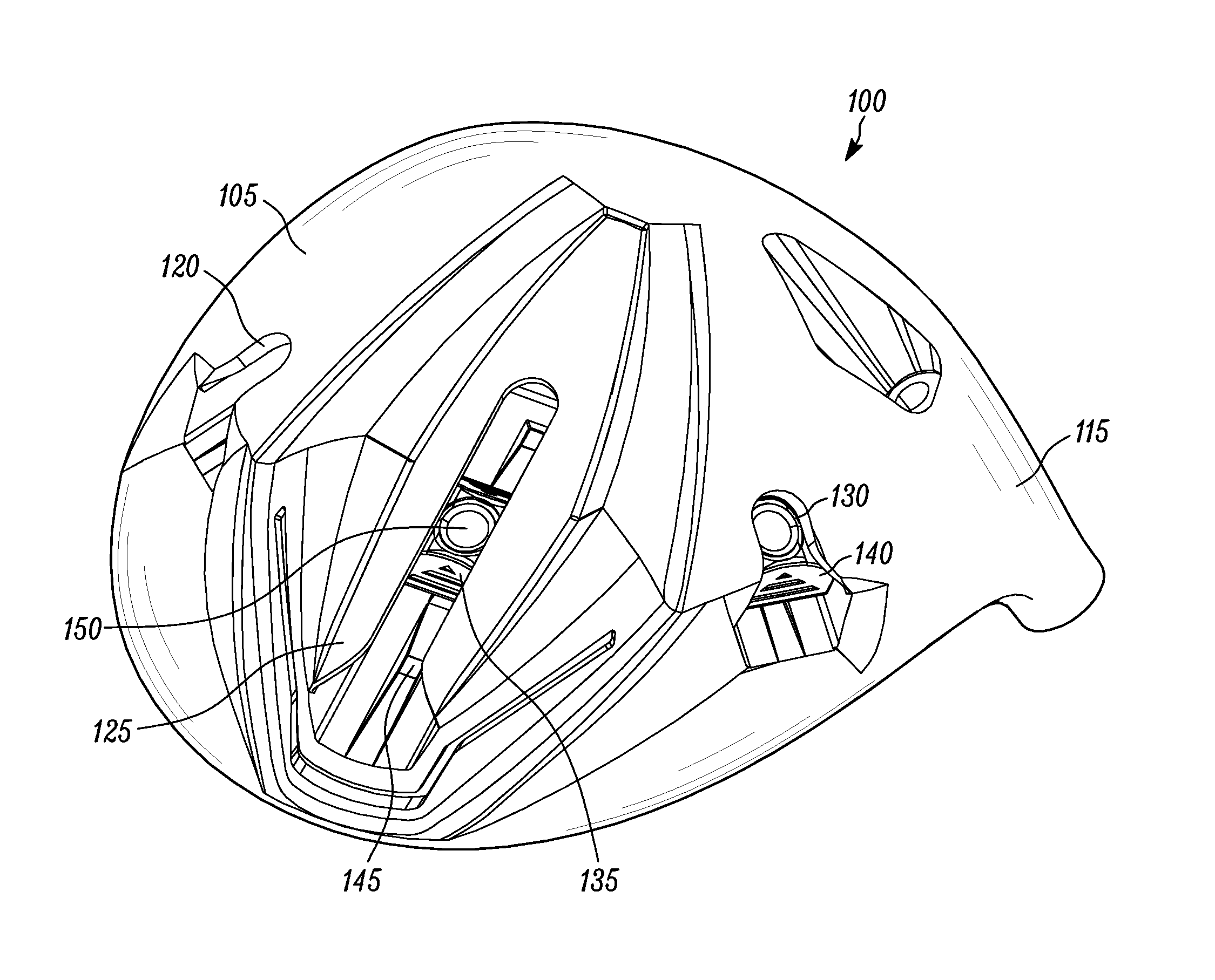
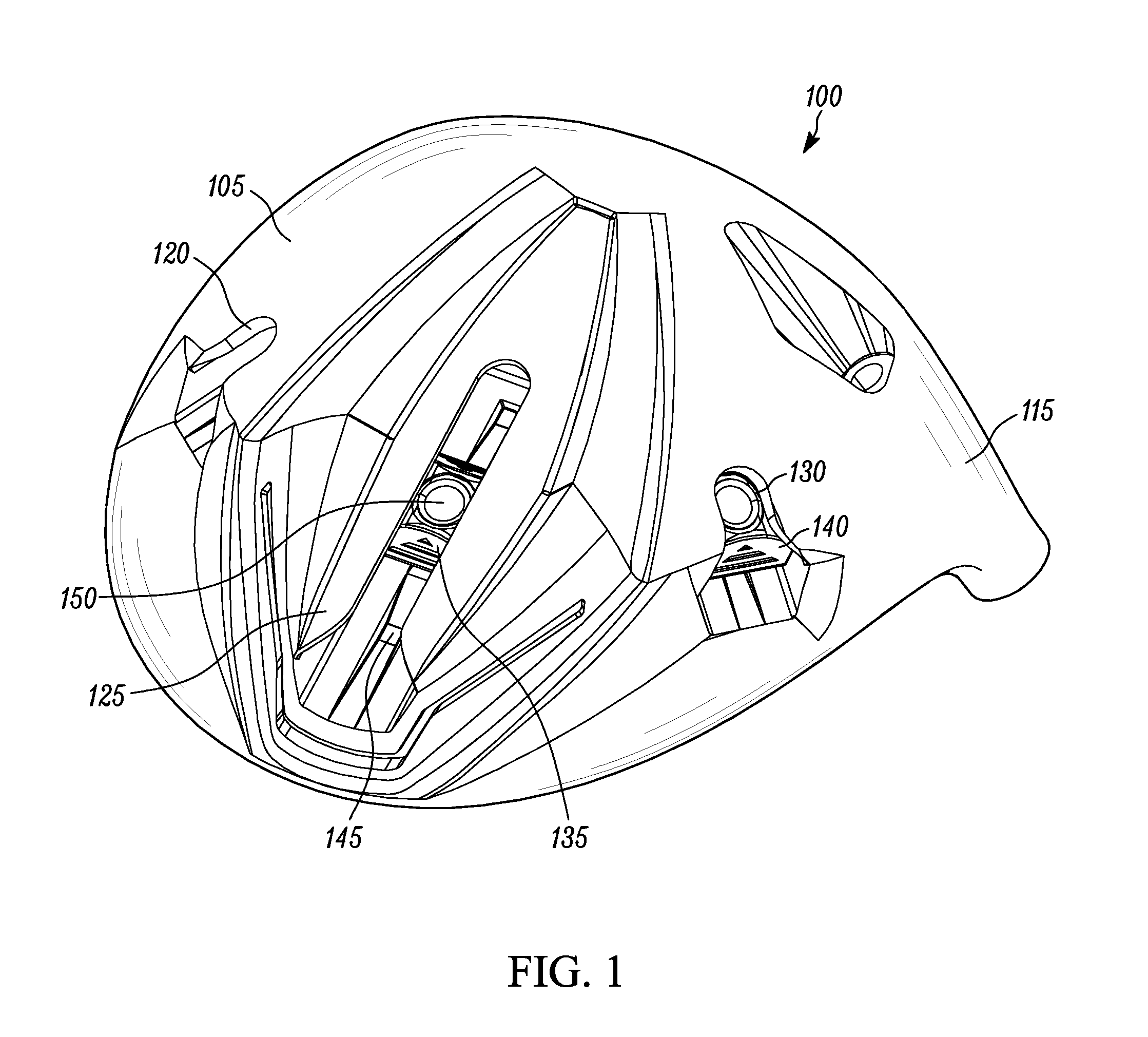
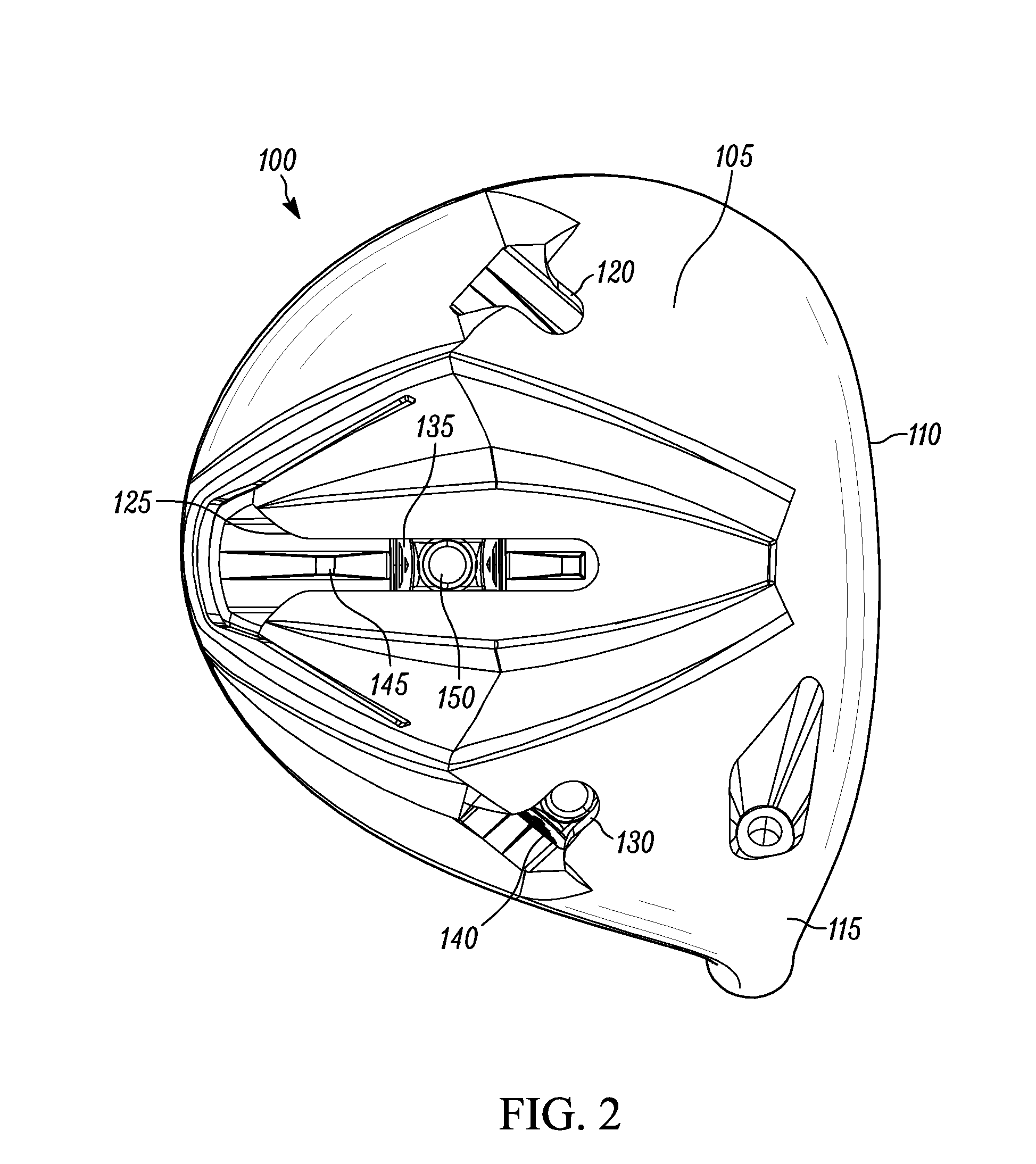
[0022]Embodiments of the present invention relate generally to golf clubs, and more particularly to adjustable golf clubs. In some embodiments, a golf club can be adjusted by moving sliders located proximate the heel of the club head. The sliders can be in communication with the shaft of the club, enabling the sliders to reposition the shaft with respect to the club head, which enables adjustment of the club. In some embodiments, a user can loosen a fastener, reposition the sliders, and tighten the fastener to rigidly lock the club in place. In this manner, the user can adjust the club.

[0023]To simplify and clarify explanation, the invention is described herein as an adjustable golf club. One skilled in the art will recognize, however, that the invention is not so limited.

[0024]The materials described hereinafter as making up the various elements of the present invention are intended to be illustrative and not restrictive. Many suitable materials that would perform the same or a sim...


PUM


Abstract

An adjustable golf club is disclosed. The adjustable golf club can include a club head having a sole. The sole of the club head may have two or more tracks located thereon. Each track can be configured to receive at least one weight. The two or more tracks may be three tracks. The three tracks can comprise an elongated central track, a first short track disposed on a first side of the elongated central track, and a second short track disposed on the second side of the elongated central track.

Description

CROSS-REFERENCE TO RELATED APPLICATION AND PRIORITY CLAIM[0001]This application claims the benefit, under 35 U.S.C. §119(e), of U.S. Provisional Patent Application No. 61 / 982,264, filed 21 Apr. 2014, entitled “MULTI-TRACK ADJUSTABLE GOLF CLUB,” the entire contents and substance of which is incorporated herein by reference in its entirety as if fully set forth below.BACKGROUND[0002]1. Field of the Invention[0003]The present invention relates generally to golf clubs, and more particularly to multi-track adjustable golf clubs.[0004]2. Background of Related Art[0005]Golfers have many different swing types. This variety in swing types means that different golfers contact the ball in different ways. Each different swing can impart a different spin and / or flight trajectory to the ball. The ball may “draw” or “fade,” for example, based on the type of swing the golfer uses. Similarly, the ball may have a trajectory that varies with the spin rate of the ball following contact. A ball with a h...

Claims


Application Information

Patent Timeline
Patent Type & Authority Applications(United States)
IPC IPC(8): A63B53/06A63B53/04
CPCA63B53/06A63B2053/0433A63B2053/0491A63B53/0466A63B53/0433
Inventor VOSHALL, CHRISLLEWELLYN, DAVIDISHIDA, KAZUYAKANAYAMA, TETSUYA
Owner MIZUNO USA
Why Eureka
Try Eureka