


Quick Research
Generate reliable direction feasibility study reports for your R&D in just a few steps.

Technical Q&A
Discover and master advanced knowledge NOW. Basics, ideas, possibilities, all at once.

Find Solutions
As an expert in R&D theories, this can generate solutions to your technical problems instantly.

Evaluate Feasibility
Analyze your overall solution with one click, know your potential R&D risks in advance.

Monitor Landscape
Get weekly tech updates, stay abreast of the latest tech innovations and key insights.
Oscillating positive expiratory pressure device
a positive expiratory pressure and oscillating technology, applied in the field of respiratory treatment devices, can solve the problems of affecting the bronchial obstruction, splitting open obstructed airways, and insufficient single cough to clear obstructions,
- Summary
- Abstract
- Description
- Claims
- Application Information
AI Technical Summary
Benefits of technology
Problems solved by technology
Method used
Image


Examples
first embodiment
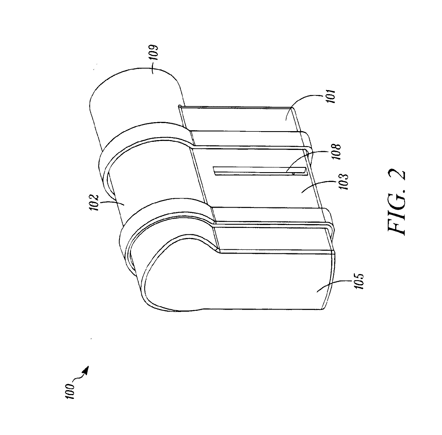
[0101]Referring first to FIGS. 1-4, a front perspective view, a rear perspective view, a cross-sectional front perspective view, and an exploded view of an OPEP device 100 are shown. For purposes of illustration, the internal components of the OPEP device 100 are omitted in FIG. 3. The OPEP device 100 generally comprises a housing 102, a chamber inlet 104, a first chamber outlet 106, a second chamber outlet 108 (best seen in FIGS. 2 and 7), and a mouthpiece 109 in fluid communication with the chamber inlet 104. While the mouthpiece 109 is shown in FIGS. 1-4 as being integrally formed with the housing 102, it is envisioned that the mouthpiece 109 may be removable and replaceable with a mouthpiece 109 of a different size or shape, as required to maintain ideal operating conditions. In general, the housing 102 and the mouthpiece 109 may be constructed of any durable material, such as a polymer. One such material is Polypropylene. Alternatively, acrylonitrile butadiene styrene (ABS) may...
second embodiment
[0128]Turning now to FIGS. 18-19, a front perspective view and a rear perspective view of a second embodiment of an OPEP device 200 is shown. The configuration and operation of the OPEP device 200 is similar to that of the OPEP device 100. However, as best shown in FIGS. 20-24, the OPEP device 200 further includes an adjustment mechanism 253 adapted to change the relative position of the chamber inlet 204 with respect to the housing 202 and the restrictor member 230, which in turn changes the range of rotation of the vane 232 operatively connected thereto. As explained below, a user is therefore able to conveniently adjust both the frequency and the amplitude of the OPEP therapy administered by the OPEP device 200 without opening the housing 202 and disassembling the components of the OPEP device 200.
[0129]The OPEP device 200 generally comprises a housing 202, a chamber inlet 204, a first chamber outlet 206 (best seen in FIGS. 23 and 32), a second chamber outlet 208 (best seen in FI...
third embodiment
[0144]Turning to FIGS. 35-37, another embodiment of an OPEP device 300 is shown. The OPEP device 300 is similar to that of the OPEP device 200 in that is selectively adjustable. As best seen in FIGS. 35, 37, 40, and 49, the OPEP device 300, like the OPEP device 300, includes an adjustment mechanism 353 adapted to change the relative position of a chamber inlet 304 with respect to a housing 302 and a restrictor member 330, which in turn changes the range of rotation of a vane 332 operatively connected thereto. As previously explained with regards to the OPEP device 200, a user is therefore able to conveniently adjust both the frequency and the amplitude of the OPEP therapy administered by the OPEP device 300 without opening the housing 302 and disassembling the components of the OPEP device 300. The administration of OPEP therapy using the OPEP device 300 is otherwise the same as described above with regards to the OPEP device 100.
[0145]The OPEP device 300 comprises a housing 302 hav...
PUM
 Abstract
Description
Claims
Application Information
 - R&D Engineer
- R&D Manager
- IP Professional
- Industry Leading Data Capabilities
- Powerful AI technology
- Patent DNA Extraction
Browse by: Latest US Patents, China's latest patents, Technical Efficacy Thesaurus, Application Domain, Technology Topic, Popular Technical Reports.
© 2024 PatSnap. All rights reserved.Legal|Privacy policy|Modern Slavery Act Transparency Statement|Sitemap|About US| Contact US: help@patsnap.com