Optical transceiver installing mt ferrule to mate with mpo connector

a technology of optical transceivers and ferrules, applied in the field of optical transceivers, can solve the problems of easy leakage of emi noises with higher frequencies from gaps and/or spaces with smaller frequencies, and achieve the effect of improving the reliability of optical coupling

Active Publication Date: 2015-10-15
SUMITOMO ELECTRIC IND LTD
View PDF0 Cites 6 Cited by
  • Summary
  • Abstract
  • Description
  • Claims
  • Application Information

AI Technical Summary

Benefits of technology

[0007]An aspect of the present application relates to an optical transceiver that comprises an optical assembly, and optical receptacle, an inner fiber, a housing, and a mechanism not only to secure an optical coupling between the optical receptacle with an external optical connector but to shield an inside of the optical transceiver reliably. The optical assembly includes an optical device. The optical receptacle couples with an external fiber through an MPO connector by receiving the MPO connector. The inner fiber couples with the optical assembly by an MT ferrule also with the optical receptacle by another MT ferrule. That is, the inner fiber provides MT ferrules in both ends thereof to couple optically with the optical assembly and the optical receptacle. The housing installs the optical assembly, the optical receptacle, the inner fiber, and the mechanism. A feature of the present application is that the mechanism pushes another MT ferrule toward the optical receptacle without degrading the EMI tolerance.
[0010]Thus, the mechanism has the enhancement of the reliability of the optical coupling with the external connector, even the external connector is an MPO connector with an MT ferrule, to be consistent with the EMI tolerance.

Problems solved by technology

As the transmission speed increase, namely, the frequency of the signals increases, which means the wavelength of the signals become shorter, the EMI noises with higher frequencies easily leak from gaps and / or spaces with smaller dimensions left in the housing of the optical transceiver.

Method used


Image

  • Optical transceiver installing mt ferrule to mate with mpo connector
  • Optical transceiver installing mt ferrule to mate with mpo connector
  • Optical transceiver installing mt ferrule to mate with mpo connector

Examples


first embodiment

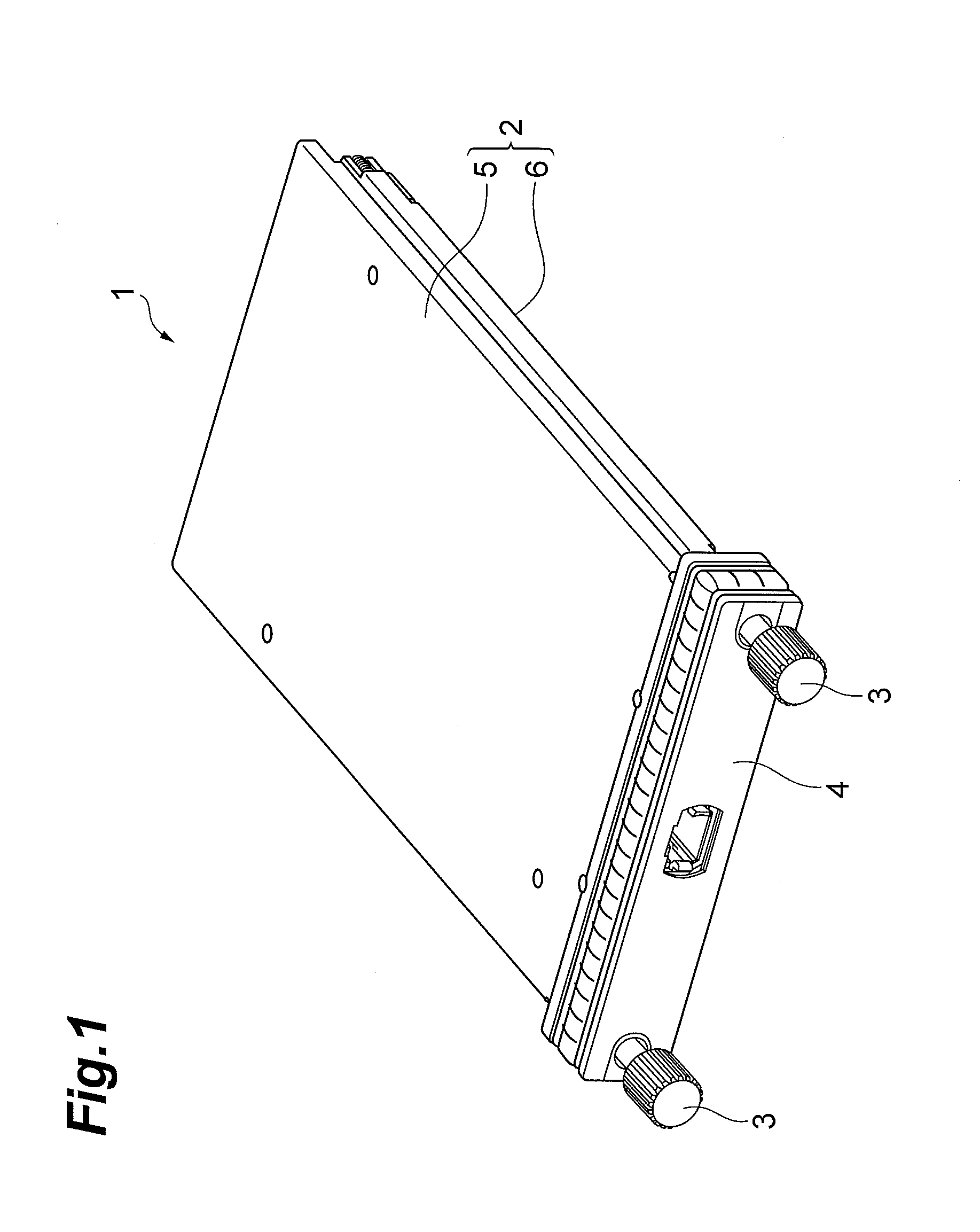
[0027]An optical transceiver 1 of the present application, as illustrated in FIG. 1, has a type of, what is called, the CFP following one of multi-source agreements (MSA) relating to optical transceivers. The optical transceiver 1, which is primarily installed in a data center, outputs and receives a plurality of optical signals via a plurality of optical fibers whose lengths are several hundred meters at most. The optical transceiver 1 implements with a plurality of vertical cavity surface emitting laser diodes (hereafter denoted as VCSEL) each emitting an optical signal with a wavelength shorter than one (1) micron as optical signal sources. The optical transceiver 1 comprises a housing 2, two screws 3, and a front cover 4. The housing 2 includes a top body 5 and a bottom body 6.

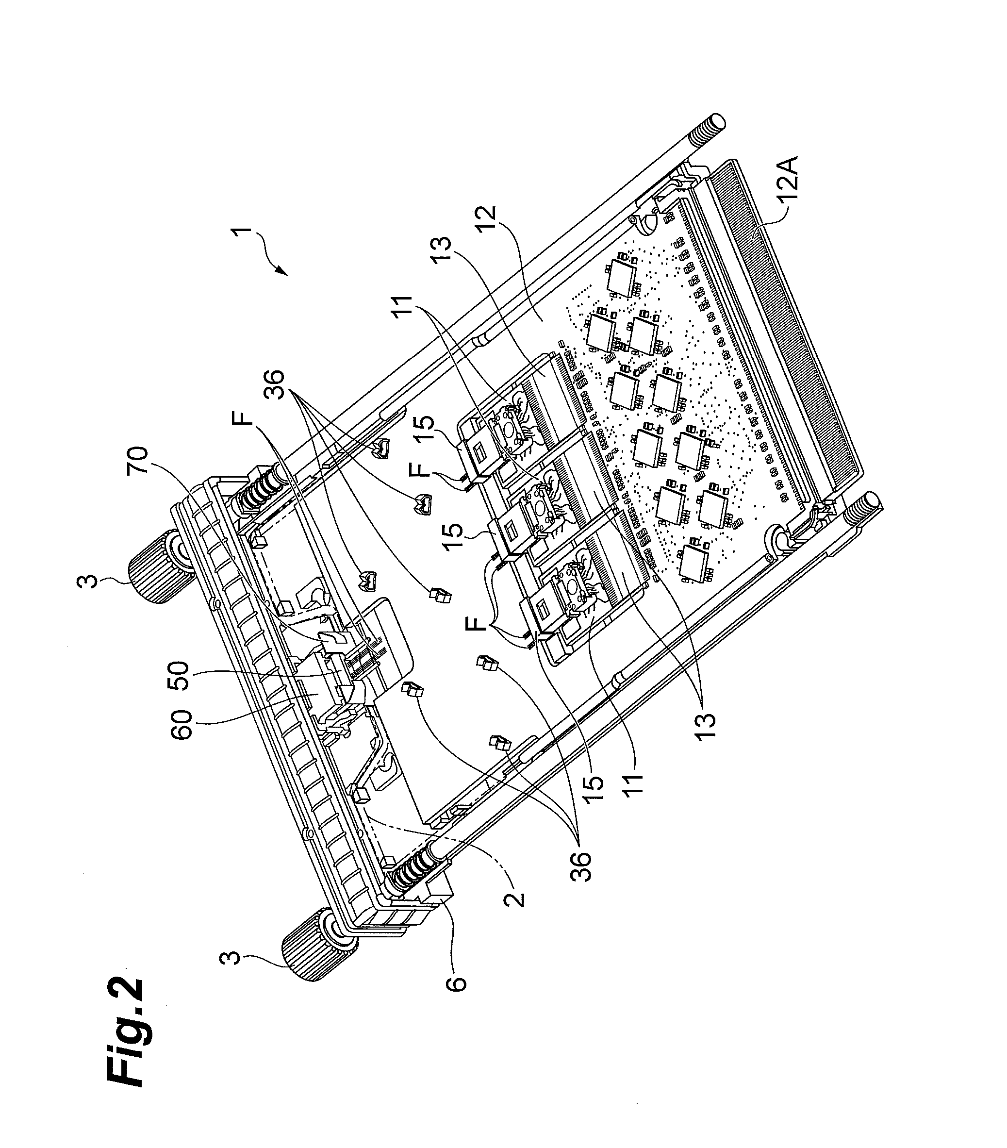
[0028]FIG. 2 is a perspective view of an inside of the optical transceiver 1. As shown in FIG. 2, the optical transceiver 1 encloses between two bodies, 5 and 6, three sub-boards 11 and a circuit board 12....

second embodiment

[0049]Next, another optical transceiver 101 according to the second embodiment of the present application will be described as referring to FIGS. 13 and 14.

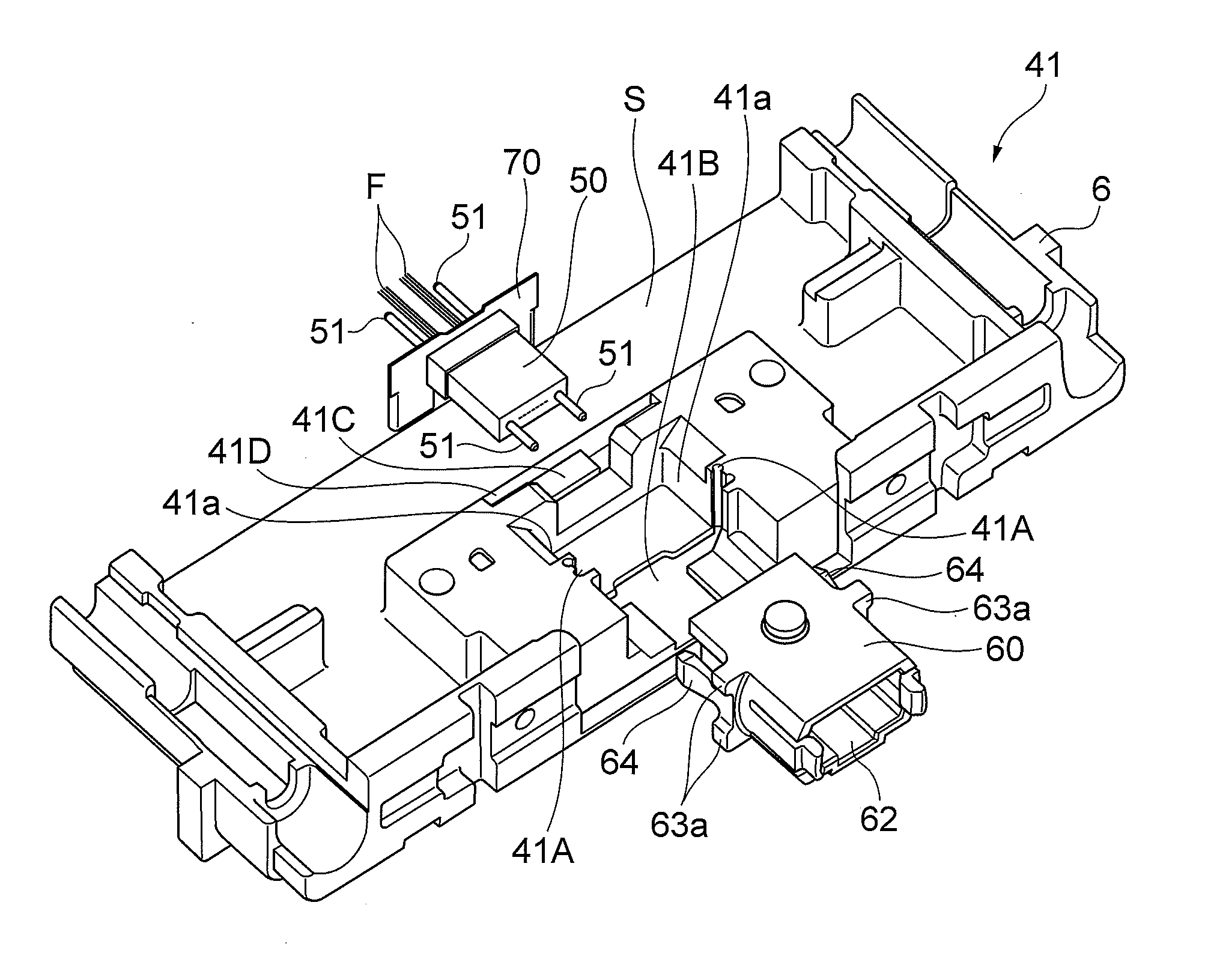
[0050]FIG. 13 is a plan view showing the inside of the optical transceiver 101 of the second embodiment. The optical transceiver 101 provides another bottom body 106 that includes a modified receptacle portion 141 with a mechanics 170 to push the MT ferrule 50 in the optical receptacle 60 instead of the plate 70 in the former embodiment. Other arrangements of the modified optical transceiver 101 are substantially same as those of former embodiment 1.

[0051]The receptacle portion 141 of the present embodiment shown in FIGS. 13 and 14, removes the terrace 41C. Instead of the terrace 41C, the receptacle portion 141 provides a hollow 141D to receive the mechanism 170 therein. The mechanism 170 includes a holder 171 with a rectangular shape to hold the MT ferrule 50 and a spring 172 to push the holder 171 against the MT ferrule 50. The...


PUM


Abstract

A pluggable optical transceiver with the CFP type and the MT ferrule is disclosed. The optical transceiver provides in a rear of the optical receptacle a mechanism to push frontward the MT ferrule set in the optical receptacle and to shield the inside of the optical transceiver. Inner fibers connecting the MT ferrule with another MT ferrule assembled with optical devices pass the mechanism, which may be a metal plate with the elastic function and / or a coil spring combined with a holder to hold the MT ferrule.

Description

BACKGROUND OF THE INVENTION[0001]1. Field of the Invention[0002]The present application relates to an optical transceiver, in particular, the present application relates to an optical transceiver that provides an MT ferrule to be mated with an external MPO (Multiple-fiber Push-ON) connector.[0003]2. Background Arts[0004]MPO connectors have been well known in the field of optical communication. A Japanese Patent Application laid open No. H10-123366A has disclosed an inner configuration of an MPO connector. The MPO connector connects fibers in one side with fibers in other sides; that is, the MPO connector optically couples a plurality of fibers collectively.[0005]On the other hand, one type of multi-source agreements (MSA) has defined details of a pluggable optical transceiver called as Centum (100) gigabit From-factor Pluggable (hereafter denoted as CFP). The CFP transceiver in an original specification thereof provides an optical receptacle types of, what is called, the LC connecto...

Claims


Application Information

Patent Timeline
Patent Type & Authority Applications(United States)
IPC IPC(8): G02B6/40
CPCG02B6/403G02B6/3885G02B6/4261G02B6/4246G02B6/4292G02B6/4201
Inventor OKI, KAZUSHIGEMATSUI, TAKASHIISHII, KUNIYUKIKAMISUGI, HIDEAKIKURASHIMA, HIROMISHAH, JIGNESHZHANG, LIN
Owner SUMITOMO ELECTRIC IND LTD
Why Eureka
Try Eureka