
Cervical Traction Device

a cervical vertebrae and traction technology, applied in the field of traction devices, can solve the problems of difficulty in breathing, affecting the arms and legs, and affecting the cord trauma of the cervical vertebrae,

Inactive Publication Date: 2015-10-15
SINGHAL BALRAJ
View PDF9 Cites 8 Cited by
  • Summary
  • Abstract
  • Description
  • Claims
  • Application Information

AI Technical Summary

Benefits of technology

The invention is a device that can be used to apply traction to the cervical vertebrae to help treat spinal issues. The device allows for traction to be applied through a wide range of angles, which can put the spine in flexion or extension or any of a range of intermediate positions. This makes it easier to adjust the spinal column to the desired position.

Problems solved by technology

Spinal cord trauma affecting the cervical vertebrae, (i.e. C1-C7 vertebrae) can be especially serious, in that it affects everything below the side of the trauma, and thus can affect the arms and legs, as well as causing breathing difficulties.
Spinal cord trauma affecting cervical vertebra is a distressingly common result of motor vehicle accidents, rugby accidents and diving accidents caused by diving into shallow water.
However, in this arrangement the weights hang freely near the end of the bed on which the patient is supported, and are vulnerable to being knocked against and displaced.
Further, once traction has been applied, the patient cannot be moved whilst under traction.
Another drawback is the force applied by the traction cannot be increased gradually, but only in set increments depending upon the size of the weights being applied.
A further drawback is that it is not possible to vary the angle at which the weights are applied to the patient.
However, none of the existing devices for applying traction allow traction to be applied through a wide angular range, so that the traction can not only be applied along a neutral line, (i.e. approximately in line with the undamaged portion of the spine), but can also be applied from above the patient so as to place the spine in flexion (i.e. forward bend), and below the patient, so as to place the spine in extension (i.e. backward bend.

Method used


Image

  • Cervical Traction Device
  • Cervical Traction Device
  • Cervical Traction Device

Examples


Embodiment Construction

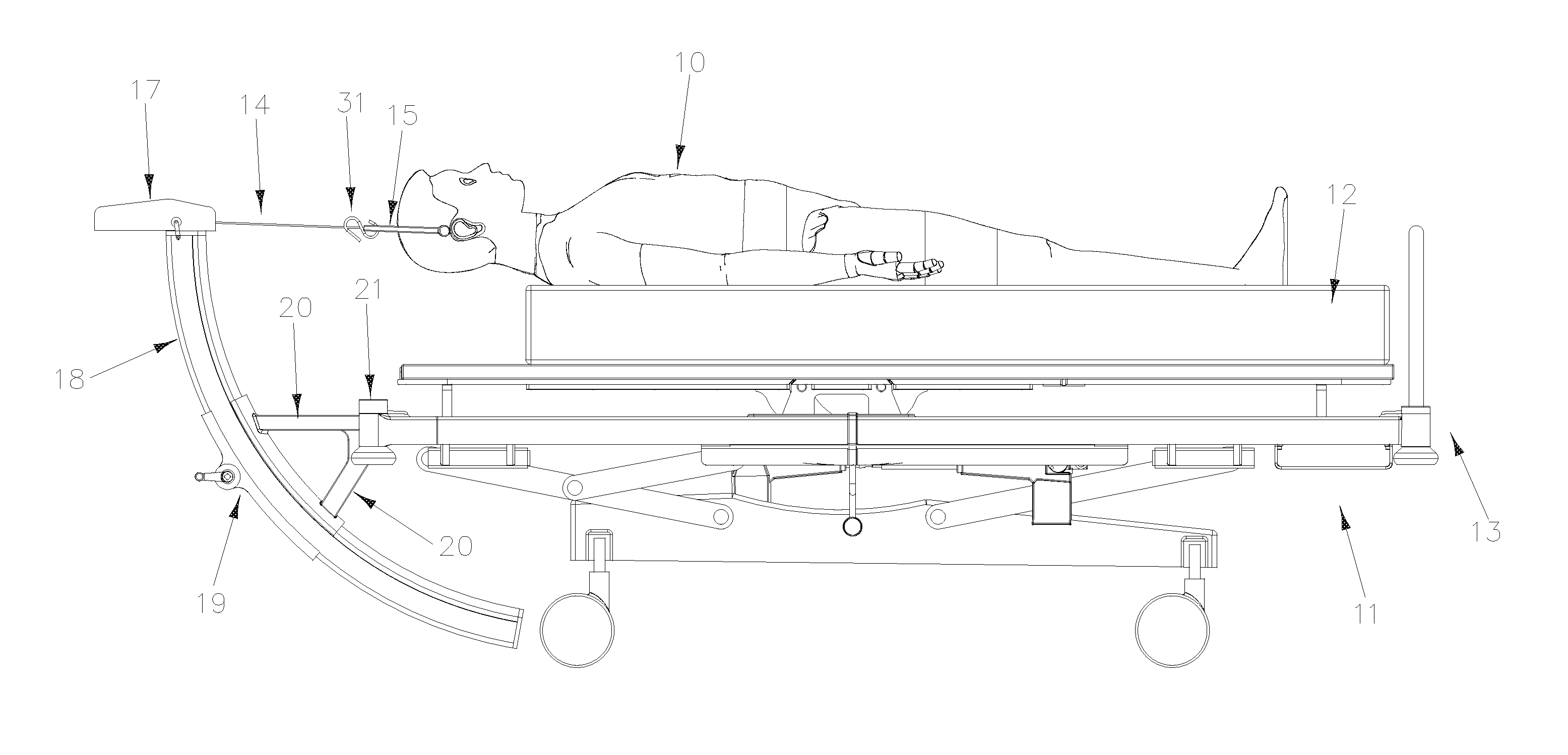
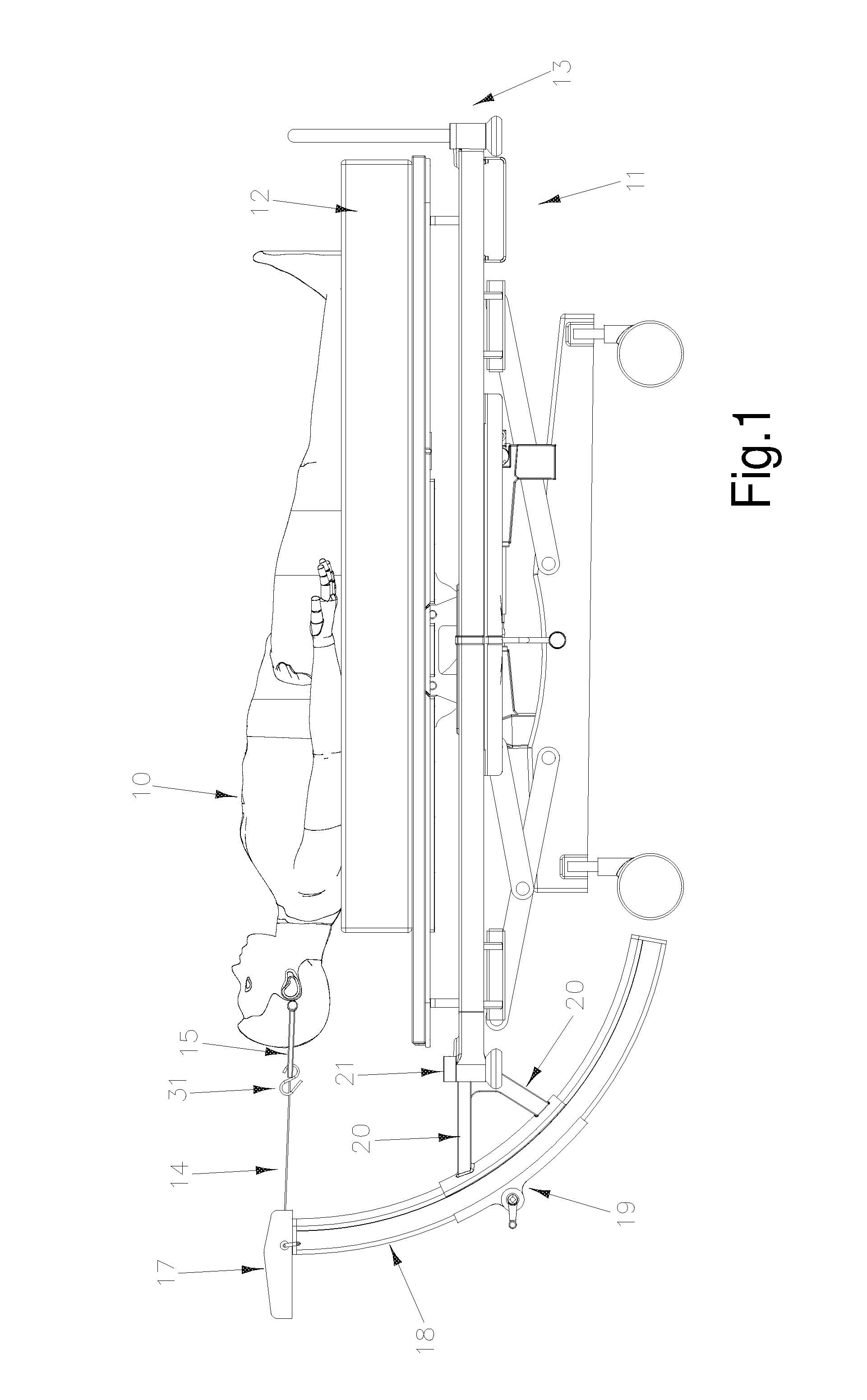
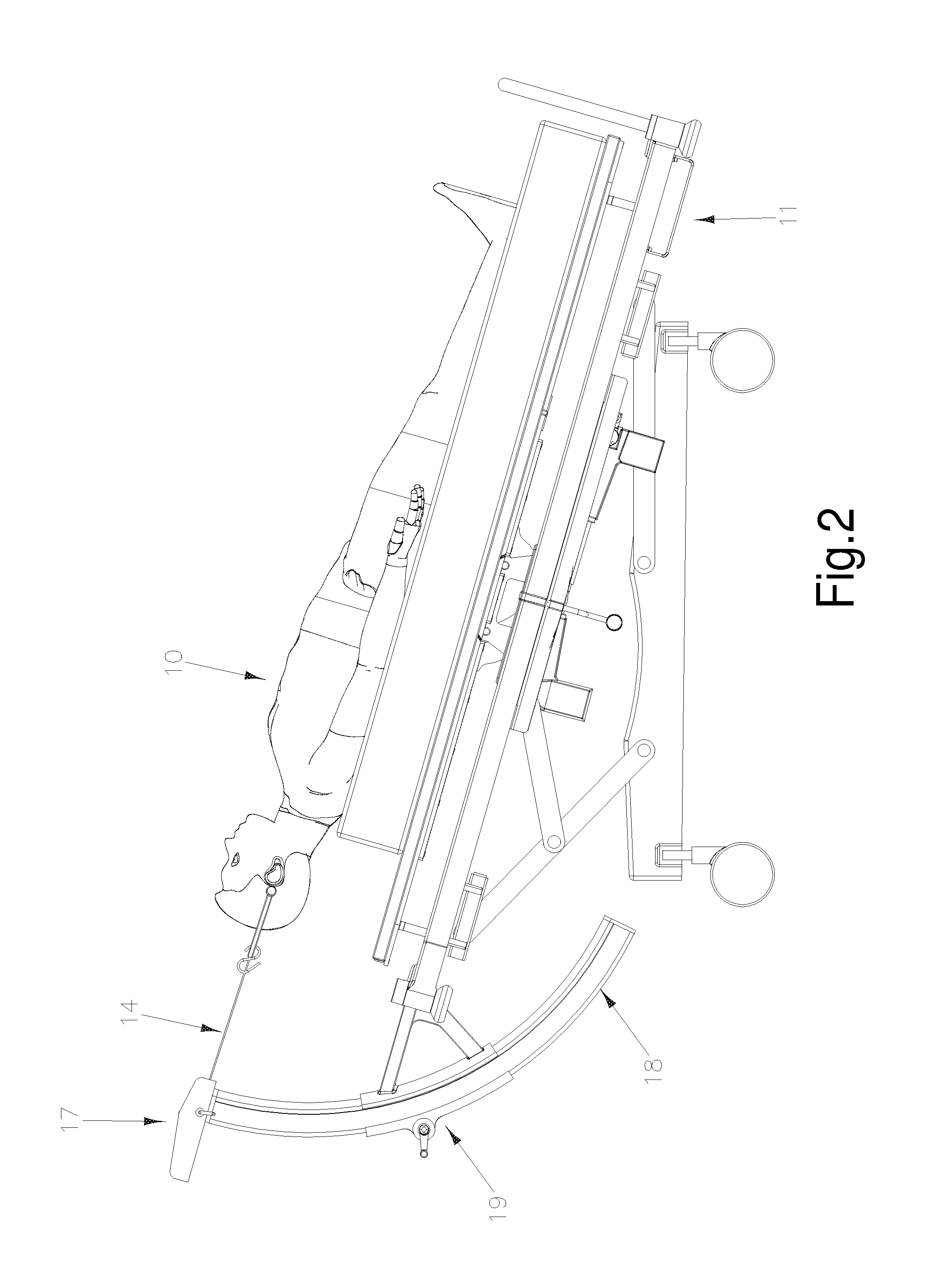
[0033]Referring to the drawings, as shown in FIGS. 1-4, a patient 10 to be treated for fracture dislocations of the cervical spine is supported upon a support surface 11 in the form of a Howard Wright trauma stretcher. The trauma stretcher is of known type, and provides a mattress 12 carried upon a mobile base 13 which can be adjusted in angle (see FIGS. 2 and 3). The base 13 can be tilted from the ‘base’ position shown in

[0034]FIG. 1, in which the plane of the base is substantially horizontal, up to a position in which the plane of the base is at about 25° to the horizontal, or even up to 45°. The base 13 also may be tilted to any of a range of positions between these extremes. The stretcher also provides means for securing the patient to the stretcher, so that traction can be applied as described below without actually pulling the patient along the stretcher.

[0035]For clarity, in the drawings the head of the patient 10 is shown unsupported, with the patient's shoulders aligned wit...


PUM


Abstract

A device for applying traction to the cervical vertebrae to reduce fracture dislocation of the cervical spine, said device including: a support surface adapted to support a patient lying upon his or her back; a load transmitting means adapted to be connected at one end to a patient under treatment and lying upon said support surface; the other end of said load transmitting means being adapted to be connected to a load applying means; said load applying means being movable along a regular or irregular curve to any of a range of predetermined positions between a first position which places the patient's cervical spine in flexion and a second position which places the patient's cervical spine in extension.

Description

FIELD OF INVENTION[0001]The present invention relates to a traction device, and in particular to a device for applying traction to the cervical vertebrae, and reducing fracture dislocations of the cervical spine.BACKGROUND OF THE INVENTION[0002]Any discussion of the prior art throughout the specification is not an admission that such prior art is widely known or forms part of the common general knowledge in the field.[0003]Spinal cord trauma can be caused by a wide range of injuries to the spine, resulting from, for example, motor vehicle accidents, falls, and sports injuries. Spinal cord trauma affecting the cervical vertebrae, (i.e. C1-C7 vertebrae) can be especially serious, in that it affects everything below the side of the trauma, and thus can affect the arms and legs, as well as causing breathing difficulties. Spinal cord trauma affecting cervical vertebra is a distressingly common result of motor vehicle accidents, rugby accidents and diving accidents caused by diving into s...

Claims


Application Information

Patent Timeline
Patent Type & Authority Applications(United States)
IPC IPC(8): A61H1/02
CPCA61H2205/04A61H1/0296A61F5/04A61G7/005A61G13/04A61G2200/327A61G13/0054A61F5/042
Inventor SINGHAL, BALRAJ
Owner SINGHAL BALRAJ
Learn More