Pressure sensor, and sensor unit provided with same
a technology of pressure sensor and sensor unit, which is applied in the direction of instruments, force/torque/work measurement, fluid pressure measurement, etc., can solve the problems of deterioration of emc performance, and achieve good emc performance and prevent adverse effects from occurring
- Summary
- Abstract
- Description
- Claims
- Application Information
AI Technical Summary
Benefits of technology
Problems solved by technology
Method used
Image
Examples
first embodiment
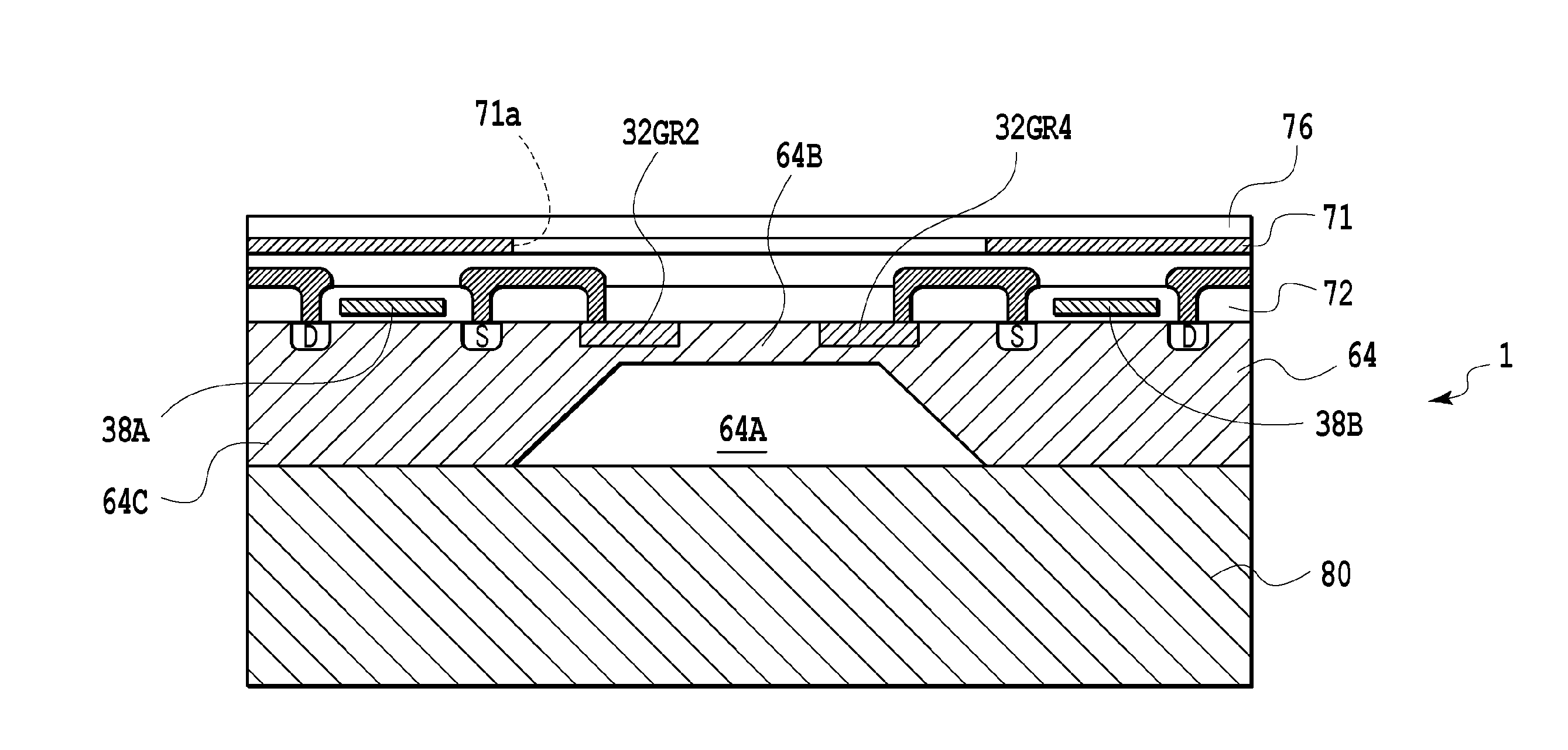
[0020]FIG. 5 schematically shows a substantial part of a pressure detection device which is adapted for a first embodiment and other embodiments described later of a pressure sensor and a sensor unit including the same according to the present invention.
[0021]In FIG. 5, the pressure detection device includes a joint unit 10 connected to piping to which a fluid subject to pressure detection is introduced, and a connector unit 12 connected to the joint unit 10 and configured to provide a detection output signal from the joint unit 10 to a given pressure measurement device.
[0022]The joint unit 10 has: a fluid introduction passage 10a communicating with the inside of the above-mentioned piping; a pressure chamber 10A formed at one end of the fluid introduction passage 10a with expanding the fluid introduction passage 10a into a conical shape; a sensor accommodating chamber formed into a cylindrical shape adjacent to the pressure chamber 10A and configured to accommodate a sensor unit to...
second embodiment
[0040]A sensor chip 1′, which is used in a pressure sensor and a sensor unit including the same according to the present invention, is schematically illustrated in FIG. 6A and FIG. 6B together with a glass layer.
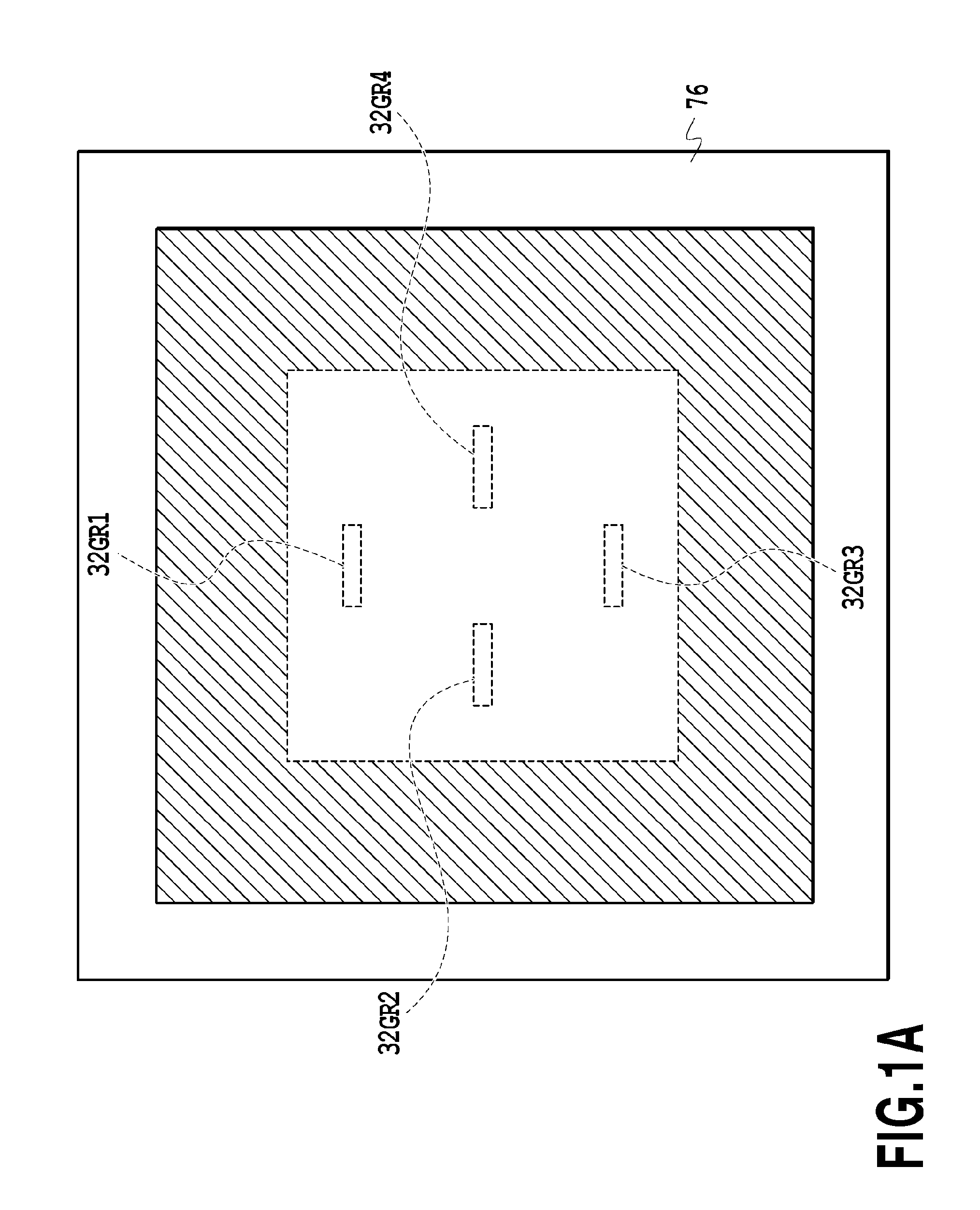
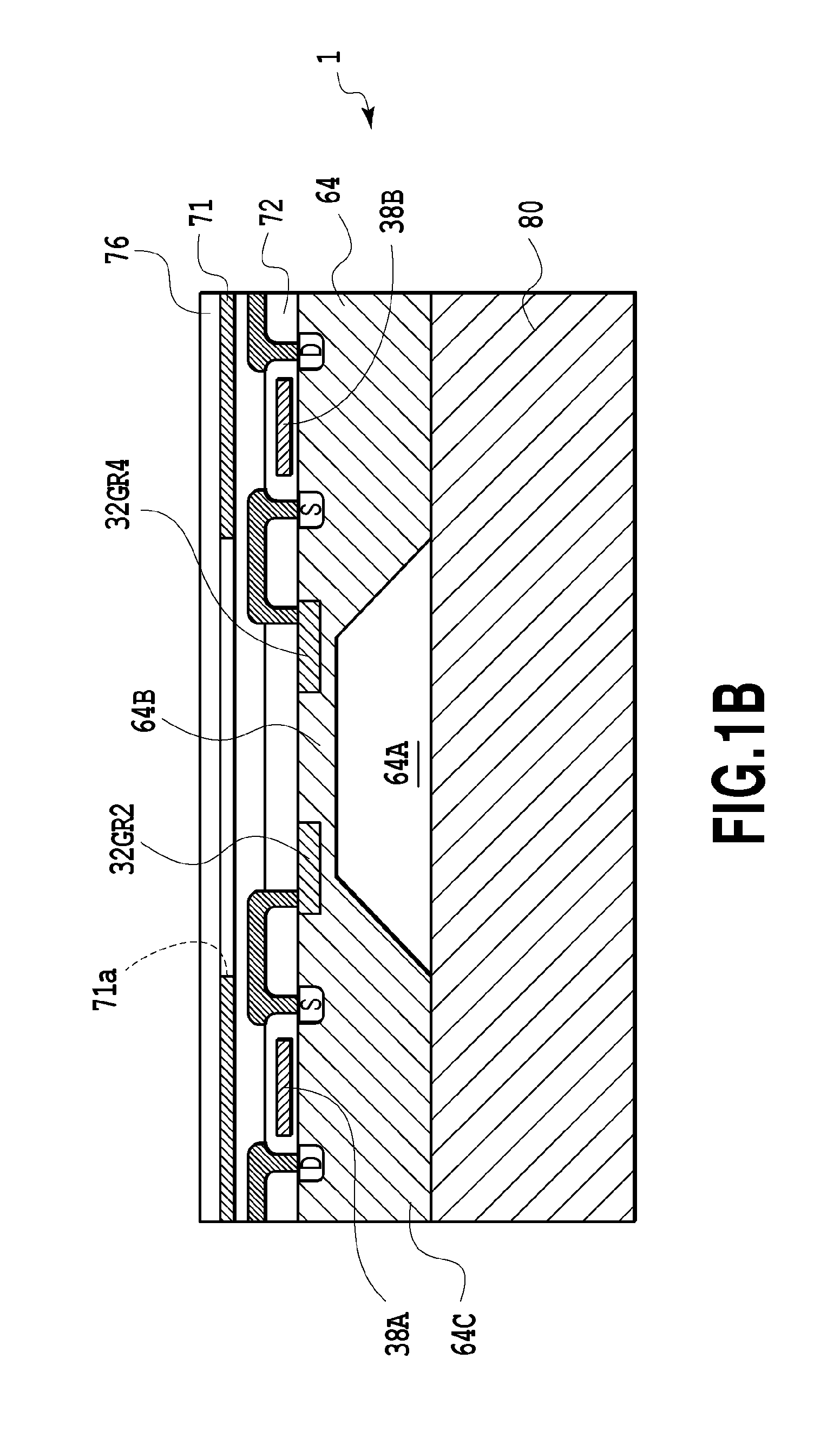
[0041]In the example shown in FIG. 1A and FIG. 1B, the shield layer 71 has the opening 71a at the position immediately above the pressure detection elements 32GR1, 32GR2, 32GR3, and 32GR4. On the other hand, in the example shown in FIG. 6A and 6B, in addition, a shield layer 73 made of polysilicon is further formed inside the opening 71a at a position immediately above the pressure detection elements 32GR1, 32GR2, 32GR3, and 32GR4.
[0042]Incidentally, in FIG. 6A and FIG. 6B, the same constituents as those in the example shown in FIG. 1A and FIG. 1B will be denoted by the same reference signs and overlapping descriptions thereof will be omitted.
[0043]As shown in FIG. 6A, for example, the shield layer 73 constituting a shield electrode is formed in a substantially rectangular r...
PUM
| Property | Measurement | Unit |
|---|---|---|
| resistance | aaaaa | aaaaa |
| resistance | aaaaa | aaaaa |
| resistance | aaaaa | aaaaa |
Abstract
Description
Claims
Application Information
 - R&D
- Intellectual Property
- Life Sciences
- Materials
- Tech Scout
- Unparalleled Data Quality
- Higher Quality Content
- 60% Fewer Hallucinations
Browse by: Latest US Patents, China's latest patents, Technical Efficacy Thesaurus, Application Domain, Technology Topic, Popular Technical Reports.
© 2025 PatSnap. All rights reserved.Legal|Privacy policy|Modern Slavery Act Transparency Statement|Sitemap|About US| Contact US: help@patsnap.com


