Projectile syringe system

a projectile syringe and syringe technology, applied in the field of injection syringes, can solve the problems of no truly inexpensive disposable projectile syringe, device disclosed by, and 533 patents can only be delivered by shafts, etc., and achieve the effects of convenient handling, low cost, and reliable operation

Inactive Publication Date: 2015-10-08
GRAY JOHN M
View PDF0 Cites 8 Cited by
  • Summary
  • Abstract
  • Description
  • Claims
  • Application Information

AI Technical Summary

Benefits of technology

The present invention is a disposable projectile syringe system that is easy to use, reliable, and economical. The syringe comes pre-sterilized and pre-attached with a needle, allowing the user to easily load the desired amount of medicament or tranquilizer. The syringe is designed to be used with various delivery systems such as guns, blow pipes, bow, and cross bows. The system includes a spring-loaded power assembly that is securely attached to the syringe and can be easily handled without releasing the compressed spring. The syringe has a smooth surface and is ready to fire from a gas or explosive gun. The invention is a significant improvement over existing projectile syringes and can be manufactured on standard injection molding machines.

Problems solved by technology

Moreover, the device disclosed by the '533 patent can only be delivered by a shaft (i.e. an arrow, cross bow, bolt or pole).
At the present time (2014), there is no truly inexpensive disposable projectile syringe.
None of the presently manufactured syringes have variable volume.
None of the syringes can be readily filled immediately after receipt from the factory without need of multitudinous assembly procedures.
World wide, at least 8 manufacturers are marketing inefficient syringes.
Most of the projectile syringes available today that claim to be reusable cannot be disassembled for cleaning.
None of the projectile syringes available today come to the user in a sterile condition.

Method used


Image

  • Projectile syringe system
  • Projectile syringe system
  • Projectile syringe system

Examples


Embodiment Construction

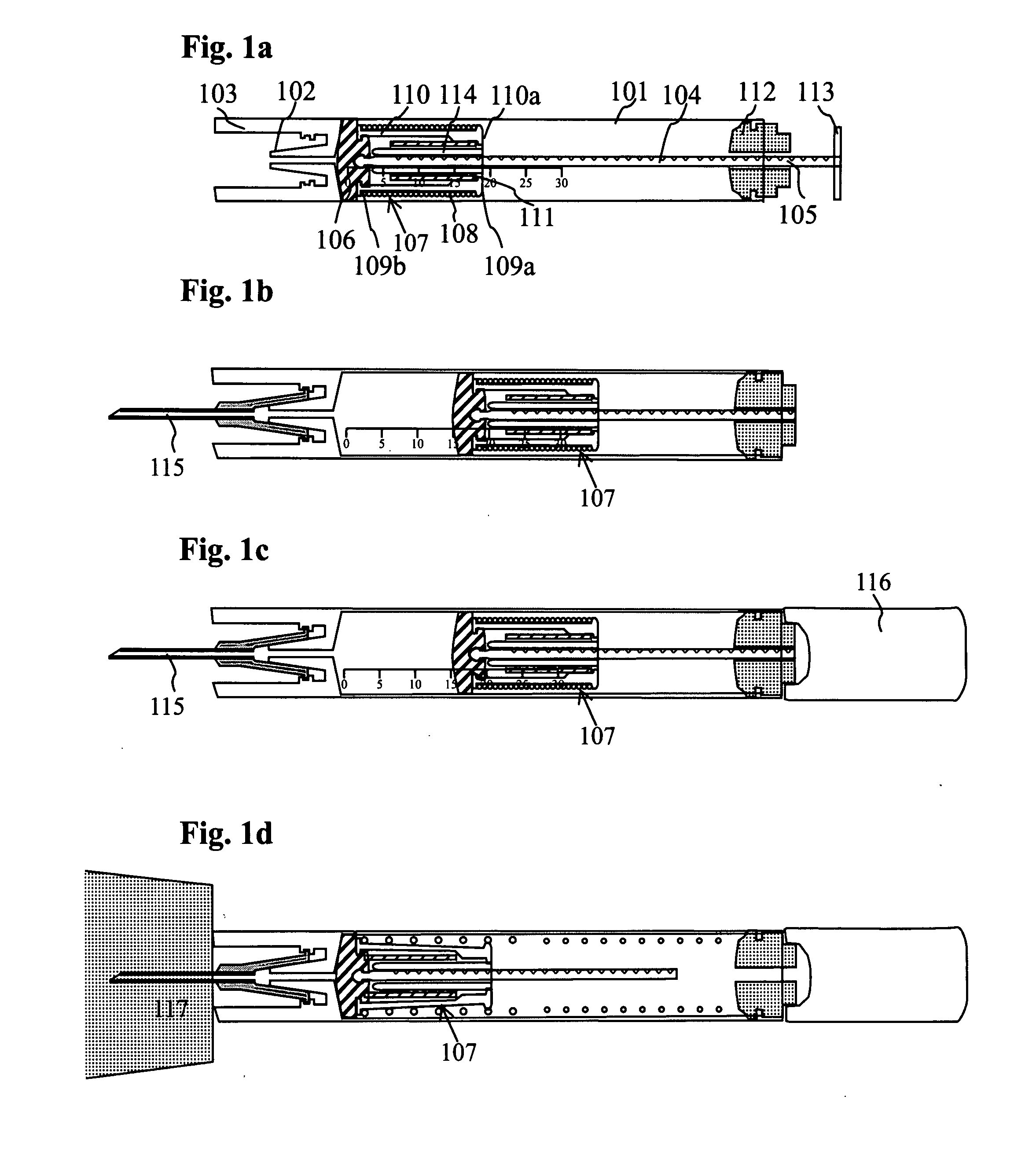
[0039]The objective of the invention is to create an inexpensive projectile syringe capable of receiving a variable quantity of medicament, as selected by the user. This feature is absent in prior art disclosures. The drive to push the plunger is not accomplished by compressed air, compressed gas or explosive charges pushing on the plunger, but rather by a compression spring that pushes against the plunger to thereby effect release of the medicament. The release of the compressed compression spring is accomplished by lateral movement of a lightweight, slidable cylindrical member.

[0040]This invention relates to a method and apparatus wherein an injection syringe may be loaded with injectable drugs or tranquilizers according to the size of animal targeted. The injection syringe is manufactured with the following key components: a) a special syringe with an extended needle receiving portion, arranged so that when the needle enters the animal on impact from a gas powered or explosive po...


PUM

PropertyMeasurementUnit
Massaaaaaaaaaa
Weightaaaaaaaaaa
Forceaaaaaaaaaa

Abstract

A projectile syringe has a barrel, a spring loaded power assembly with an attached plunger, a notched plunger shaft terminating in a knob and a breach plug secured to the barrel. The spring loaded power assembly has a cylindrical sleeve with four dissected fingers, two projections on the sleeve's outer cylindrical surface securing a compressed compression spring. A cylindrical weight is captured within the sleeve by four fingers. The user attaches a needle and draws a desired amount medicament. The plunger shaft is broken flush against the breech plug. The user attaches a stabilizing tail to the breech plug end and the projectile syringe is aimed at a target animal. Stopping the syringe displaces the cylindrical weight, allowing the four fingers to displace. The proximal projections move inward, allowing the compressed compression spring to expand to the fixed breech plug, pushing the piston to deliver medicament to the animal.

Description

1. FIELD OF THE INVENTION[0001]The present invention relates to a method and device for remote injection of fluids; and, more particularly, to an injection syringe that may be easily loaded with selected amount of injectable drugs or tranquilizers according to the size of a targeted animal and delivered using a gun or other delivery mechanism.2. DESCRIPTION OF THE PRIOR ART[0002]Numerous prior art patents and disclosures relate to injectable syringes that may be projected towards an animal. The amount of injectable drugs or tranquilizers is fixed according to the size of the injection syringe chosen and this amount may not be selected according to the type and size of the animal.[0003]U.S. Pat. No. 4,106,770 to John M. Gray discloses a hypodermic syringe projectile. This hypodermic syringe projectile is characterized by a hollow housing which receives an axially movable body member. A chamber for receiving treatment liquid is defined between an end of the body member and an end of t...

Claims


Application Information

Patent Timeline
IPC IPC(8): A61D7/00F42B12/54
CPCA61D7/00Y10T29/49826F42B12/54
Inventor GRAY, JOHN M.
Owner GRAY JOHN M
Why Eureka
Try Eureka