
Connector

Active Publication Date: 2015-10-01
SUMITOMO WIRING SYST LTD
View PDF12 Cites 2 Cited by
  • Summary
  • Abstract
  • Description
  • Claims
  • Application Information

AI Technical Summary

Benefits of technology

The invention is a connector with a housing and locking lances that secure terminal fittings. The locking lances have deflection spaces to allow them to move resiliently. A front retainer and two plate-like functional portions are assembled on the housing, with at least one reinforcing rib to enhance flexural rigidity. The reinforcing ribs may be on the upper and lower surfaces of the supporting plate and may connect with opposite side walls of the housing. The groove is formed by recessing only the lower surface of the plate-like functional portion. The technical effects are increased flexural rigidity and strength of the connector housing and components.

Problems solved by technology

However, the supporting plate is not connected to side walls that partition the cavities in a lateral direction.
Thus, the reliability of a correcting function is low.

Method used


Image

  • Connector
  • Connector
  • Connector

Examples


Embodiment Construction

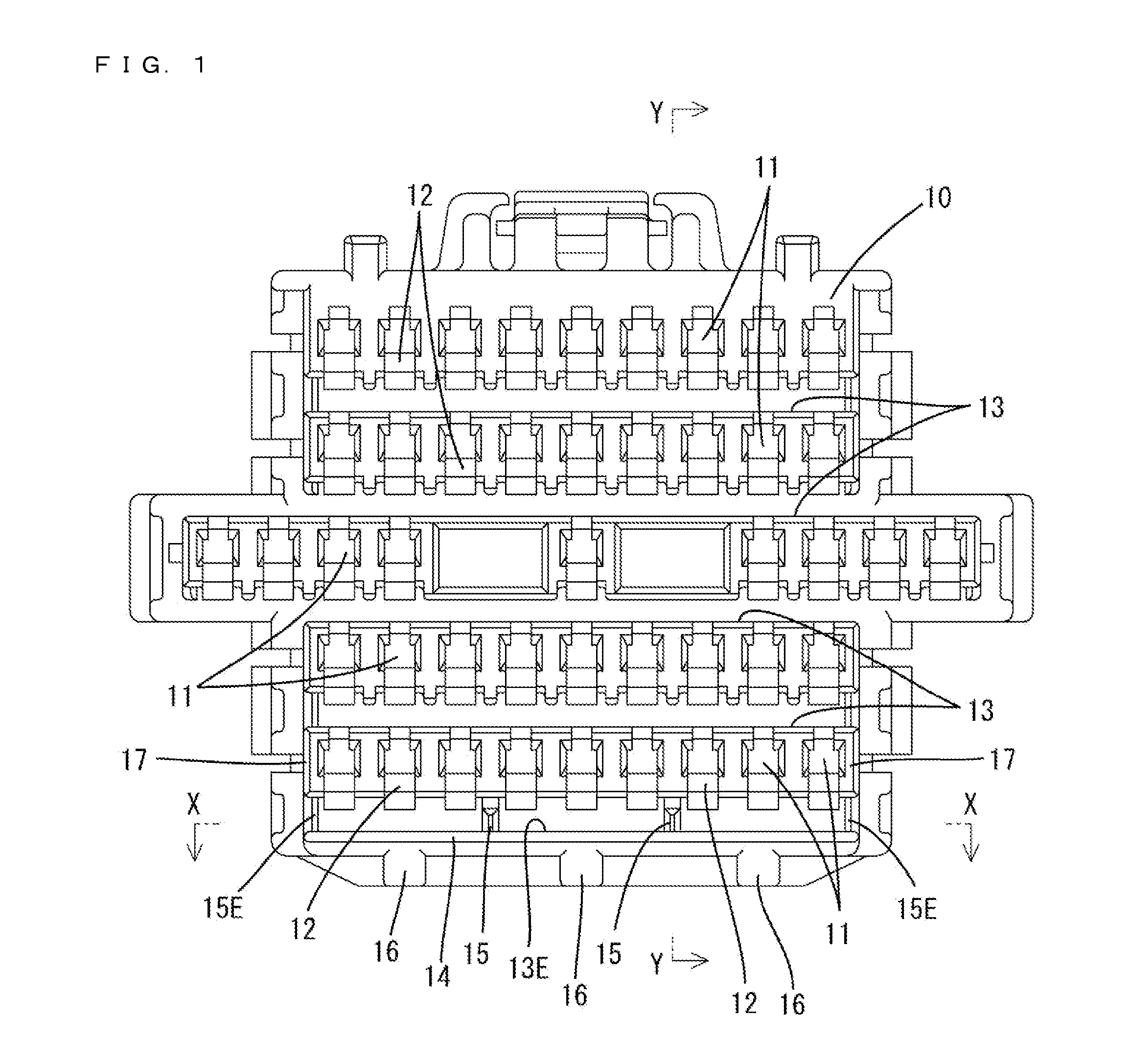
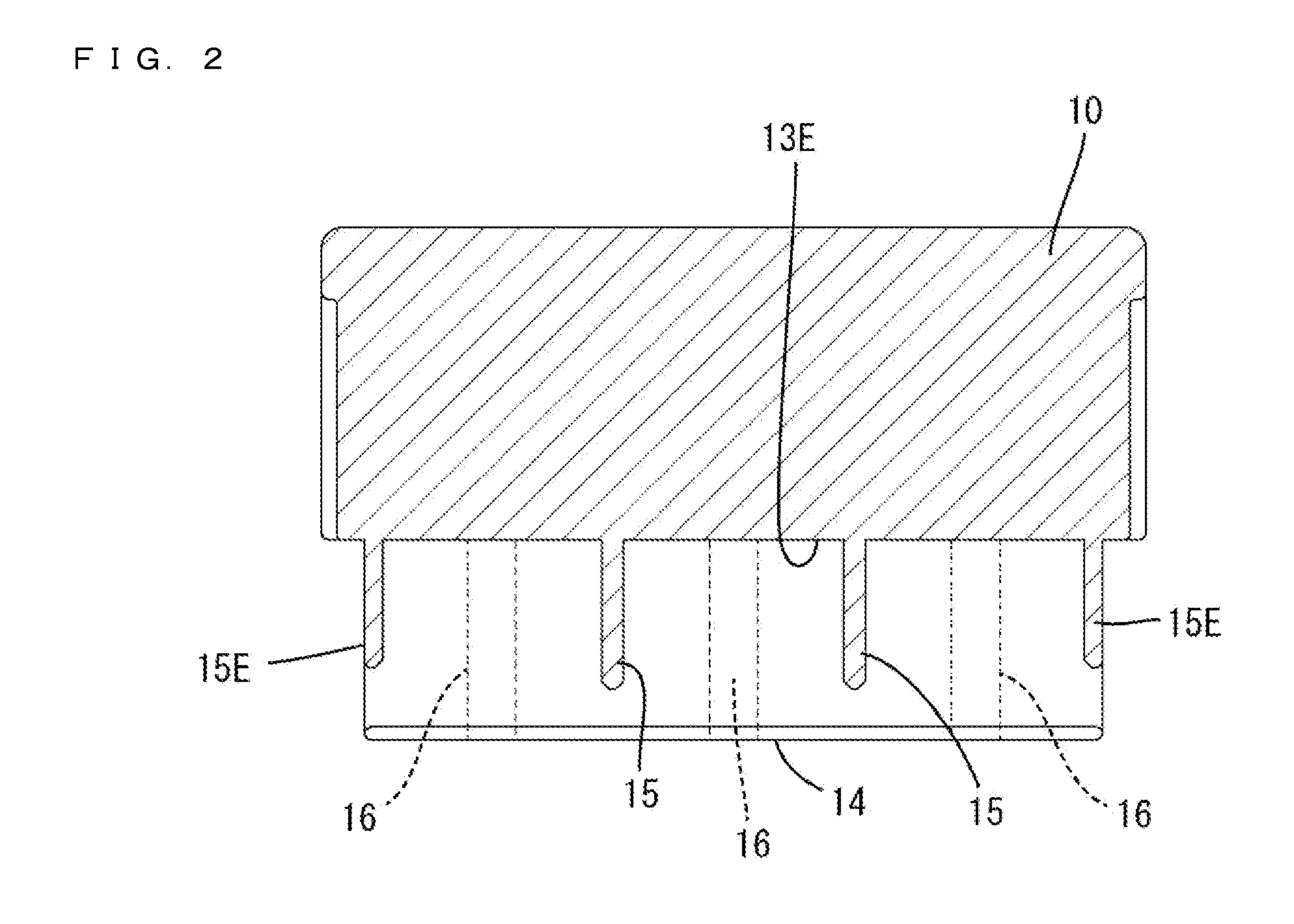
[0021]An embodiment of the invention is described with reference to FIGS. 1 to 8. A right side in FIGS. 3, 5 and 7 is defined as a front end concerning a front-back direction. Upper and lower sides in FIGS. 1 and 3 to 5 are defined as upper and lower sides concerning a vertical direction. A lateral direction in FIGS. 1 and 4 is defined as the lateral direction.

[0022]A female connector F of this embodiment is formed by assembling a housing 10 made of synthetic resin, a front retainer 20 made of synthetic resin and a plurality of terminal fittings 30.

[0023]As shown in FIGS. 1 and 8, terminal accommodating chambers 11 penetrate the housing 10 in the front-back direction and are formed in multiple stages in the vertical direction. The terminal accommodating chambers 11 in each stage are arranged side by side at predetermined intervals in the lateral direction. As shown in FIG. 8, a locking lance 12 is cantilevered forward along a lower surface of each terminal accommodating chamber 11. ...


PUM


Abstract

A connector (F) includes a housing (10) formed with terminal accommodating chambers (11) in multiple stages in a vertical direction. Locking lances (12) cantilever forward along lower wall surfaces of the terminal accommodating chambers (11), and terminal fittings (30) are retained by the locking lances (12). Deflection spaces (13, 13E) allow the locking lances (12) to be resiliently deflected. Horizontal plate-like functional portions (21, 21E) are formed on a front retainer (20) and are insertable into the deflection spaces (13, 13E). A supporting plate (14) is cantilevered forward along a lower surface of the lowermost plate-like functional portion (21, 21E) and constitutes an outer wall of the housing (10). Reinforcing ribs (15, 15E) and (16) are formed on the supporting plate (14) and are configured to enhance flexural rigidity of the supporting plate (14).

Description

BACKGROUND[0001]1. Field of the Invention[0002]The invention relates to a connector.[0003]2. Description of the Related Art[0004]Japanese Unexamined Patent Publication No. 2005-166608 discloses a connector including a housing formed with cavities in multiple stages in a vertical direction. Locking lances are cantilevered forward along lower surfaces of the respective cavities. Terminal fittings can be inserted into the cavities from behind and are locked by the locking lances. A front retainer is assembled with the housing from the front and horizontal restricting plates formed on the front retainer are inserted into deflection spaces for the locking lances. Insertion of the restricting plates into the deflection spaces for the locking lances restrict deflection of the locking lances away the terminal fittings and reliably retain the terminal fittings.[0005]A lower surface side of the lowermost restricting plats is covered by a supporting plate constituting an outer wall of the hous...

Claims


Application Information

Patent Timeline
IPC IPC(8): H01R13/422
CPCH01R13/4223
Inventor UCHIYAMA, YOSHIHIROMATSUURA, JUNYA
Owner SUMITOMO WIRING SYST LTD
Learn More