
Methods and systems for active load weight for mining excavating equipment

a technology of active load weight and mining excavating equipment, which is applied in the direction of instruments, specific gravity measurement, image enhancement, etc., can solve the problems of increased excavation cycle time, safety hazards, and increased overall labor and maintenance costs

Active Publication Date: 2015-10-01
SIEMENS IND INC
View PDF9 Cites 41 Cited by
  • Summary
  • Abstract
  • Description
  • Claims
  • Application Information

AI Technical Summary

Benefits of technology

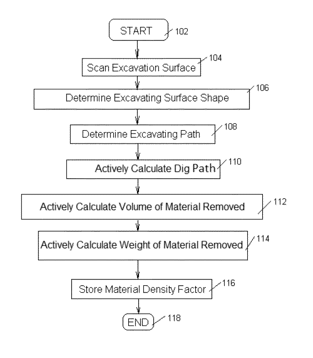
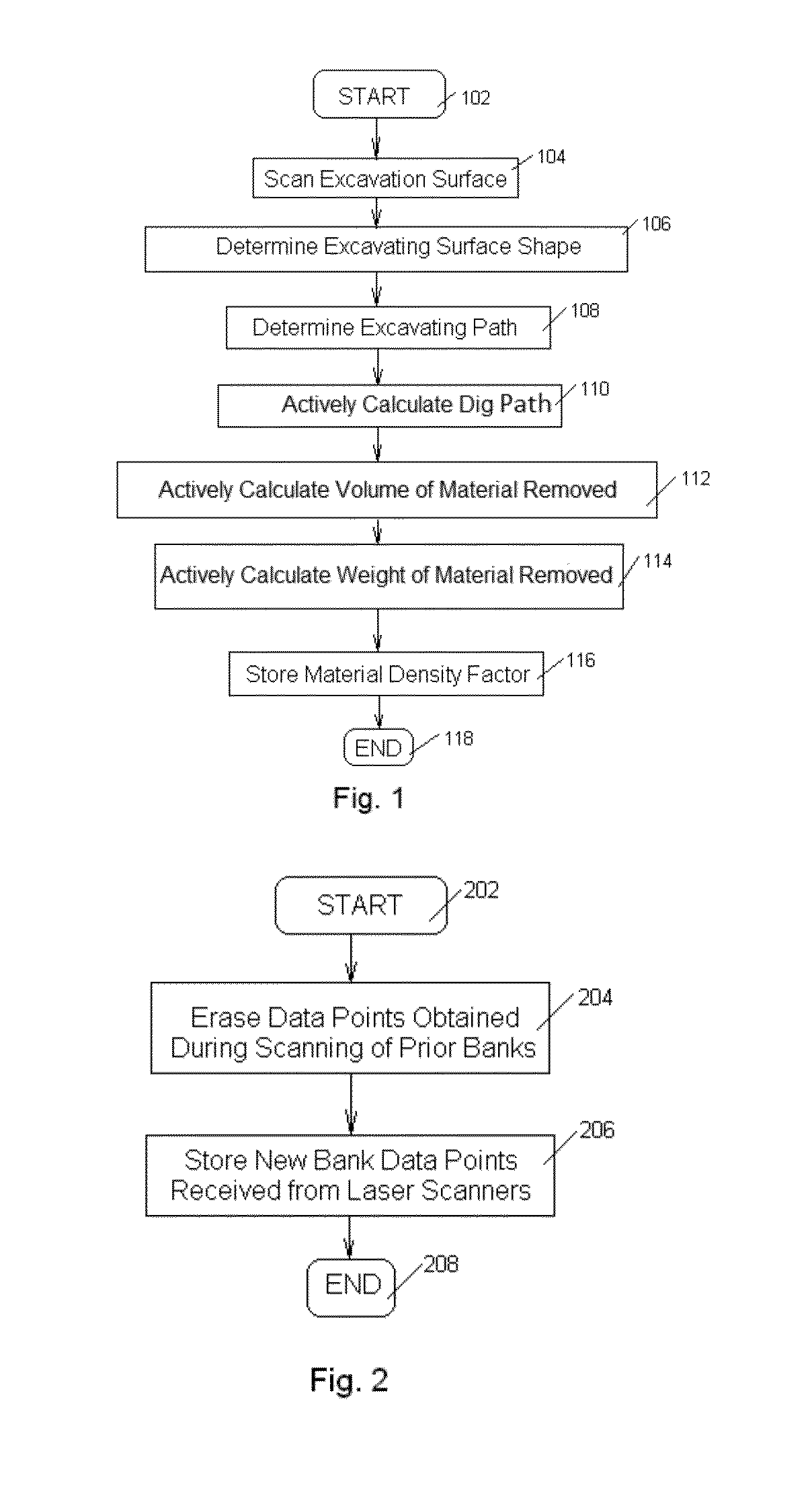
The present invention provides methods and systems for actively determining the weight of material excavated by mining equipment. This is achieved by scanning the excavation surface and using data on the shape of the surface and the path of the equipment to calculate the volume of material excavated. A density factor is then used to determine the weight of the material. This technology helps ensure more efficient and accurate mining operations.

Problems solved by technology

However, upon determining that the net weight of the load exceeds required weight, the excavation equipment may be forced to dump the excavated material, causing the increase of an excavation cycle time, creating a safety hazard and, thus, higher overall labor and maintenance costs.

Method used


Image

  • Methods and systems for active load weight for mining excavating equipment
  • Methods and systems for active load weight for mining excavating equipment
  • Methods and systems for active load weight for mining excavating equipment

Examples


first embodiment

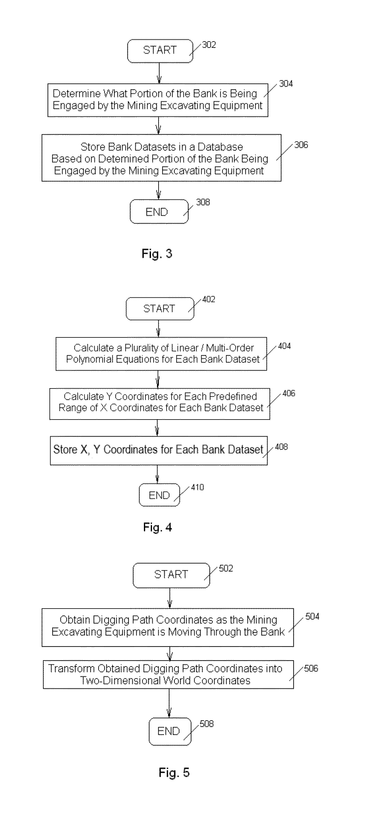
[0029]FIG. 4 illustrates a method 400 for calculating a bank shape according to a The method 400 can be used to implement a second portion of step 106 of method 100 illustrated in FIG. 1. The method 400 starts at step 402 upon conclusion of the method 300 for determining a dig face. At step 404, a plurality of linear or multi-order polynomial equations is calculated. Specifically, using the data points received for the bank path, linear or polynomial equations are calculated to represent each of the curves of the bank path and digging path. In an embodiment, in order to increase calculation accuracy, the curves of each of the bank path and digging path are not represented by a single equation. Instead, each of the bank path and digging path are parsed into small sub segments of the curves and coefficients for each small portion of each curve are calculated. Calculating coefficients for each small portion of the curves will result in anomalies affecting only coefficients in small ar...

second embodiment

[0041]A method for calculating the volume of the material in the bucket employs a 3D model of the bank represented in voxels. This method can be used in place of the volume calculation at step 804 of FIG. 8. FIG. 14 illustrates a voxel—a 3D-shaped box that is either turned “on” or “off.” If any laser scanner, used to scan the bank illustrated on FIG. 15, detects an object within a certain voxel, this voxel is considered to be in the ‘on’ state (shaded and containing the “x” mark boxes). Voxel sizes are controlled by the user and will depend on the environment and the type of laser scanners.

[0042]With the bank being represented in voxels, the digging path and the bank shape can be compared. FIG. 16 illustrates a side view of a bank (voxels in the ‘on state’ represented in shaded boxes containing the “x” mark and designated as “1”) and the digging path (shown by line “2”). It is to be understood that since the laser scanners cannot scan through material, the only part of the bank tha...


PUM


Abstract

Provided is a method in which an excavation surface is scanned, the excavation surface shape is determined based on scanned excavation surface, an excavating path is identified from a mining excavation equipment, a volume of a material excavated by the mining excavation equipment is actively calculated based at least on the excavation surface shape and the excavating path of the mining excavating equipment, and a weight of the material excavated by the mining excavating equipment is actively calculated based on at least one density factor.

Description

BACKGROUND[0001]1. Field[0002]Aspects of the present invention relate to heavy equipment for surface mine field loading operations such as human-operated and / or autonomous mining shovels, draglines, and the like, and more particularly to systems used on such equipment to actively measure the net weight of excavated material in each load.[0003]2. Description of Related Art[0004]In large scale surface mining operations, excavating equipment of immense proportions is used to excavate and load material. Excavation is usually performed by mining shovels with a bucket capacity of dozens of tons per scoop.[0005]Measurement systems have been developed to determine the net weight of material in the mining shovel bucket as it is transferred to the truck. However, upon determining that the net weight of the load exceeds required weight, the excavation equipment may be forced to dump the excavated material, causing the increase of an excavation cycle time, creating a safety hazard and, thus, hi...

Claims


Application Information

Patent Timeline
IPC IPC(8): G01G9/00G01N9/00G01G19/00G06T7/00G06T7/60
CPCG01G9/00G06T7/0075G06T7/602G06T2207/30181G01N9/00G06T2207/10012G01G19/00E02F9/261E02F9/264G01G19/08G01F17/00G01F22/00G01G23/163
Inventor JAEGER, JULLIAN D.
Owner SIEMENS IND INC
Learn More